Hydrostatic or Hydraulic Pressure Testing is a non-destructive test used to prove the integrity of a hydraulic pipework system or vessel, ensuring no leaks or pressure loss.
This non-destructive testing method uses a medium of water introduced to the system before being pressurized via a hand pump to a calculated or specified pressure.
This article will cover many areas relating to what it is, how it works, types of systems deployed upon, guidelines/regulations, calculation method, testing method, tolerances, checklists/requirements, reports, certification, templates, and general questions are asked.
🟩 What Is Pressure Testing
Hydrostatic (or hydraulic) pressure testing evaluates the strength, integrity, and reliability of pipework, vessels, and other components designed to contain fluids or gases.
After the pipework, components, and system have been installed and inspected, it will be filled with a liquid – typically water – before pressuring it to a specified or calculated level. This pressure will normally be above the system’s maximum operating pressure to check for any leaks, deformations, or weaknesses.
The pressure is then held for a specified and agreed amount of time to allow any issues to appear, which, if any are noted, will be addressed before the system is put into service.
From a safety point of view, pressure testing is also used as a safety measure to ensure that components can safely withstand the pressures they will encounter during these normal operations.
Use the table of contents to navigate this article and locate the Pressure Testing Certificate and Template Method Statement that can be downloaded.
🟩 Can Hydrostatic Testing cause damage to a System
Yes, hydrostatic pressure testing a system can, if not completed by experienced operatives and engineers who fully understand the requirements, cause damage. Sometimes catastrophic, life-threatening, and extremely expensive.
🟩 What Testing Methods Can Be Used
The testing method can be different depending on the type of system, materials used, the fluid being transported, and other safety factors.
If we concentrate on normal practice, in a standard commercial construction project, water is usually transported, so there would be three types of testing methods that could be utilized:
- Hydraulic Pressure Test only
- Pneumatic Leak Test followed by a Hydraulic Pressure Test
- Pneumatic Leak Test followed by a Pneumatic Pressure Test
To read more on Pneumatic Pressure Testing see our article 'LOW PRESSURE PNEUMATIC TEST | Prior to Hydraulic Testing'
🟩 When would you ONLY use a Hydraulic Pressure Test
Completing only a hydraulic pressure test is quite common, omitting the pneumatic, but should be conducted only once an evaluation has been conducted to understand if there are any risks with the surroundings in case of failure – resulting in damage to existing installations or furnishings.
If there are no risks, then this would be acceptable; if any hazards are noted, a pneumatic test should be conducted prior.
🟩 Other Phrases For Pressure Testing
We have all encountered different phrases used when doing this type of when depending on where we are. Here are a few we have heard; drop us a line on Linkedin if you have any others that can be added:
- Pipework pressure testing,
- Hydrostatic pressure testing,
- Hydronic testing,
- Water pressure testing,
- Hydrostatic leak testing,
- Hydrostatic burst testing,
- Water line testing.
🟩 Pressure Testing Definitions
There are a few definitions, as below, that we need to understand and will aid us in our understanding:
| WORDING | DEFINITION |
|---|---|
| Maximum Working Pressure | Maximum working pressure' is defined as the 'maximum pressure in the system during normal operation' and comprises of: 1. System Static Pressure [head or height of the system]. 2. System Pump pressure. The maximum working pressure is likely to be at the base of the system where the systems static pressure is greatest - very important if dealing with high-rise buildings, etc. |
| Testing Pressure | The test pressure is the pressure to be applied to the system during pressure testing under static conditions [pumps not running]. |
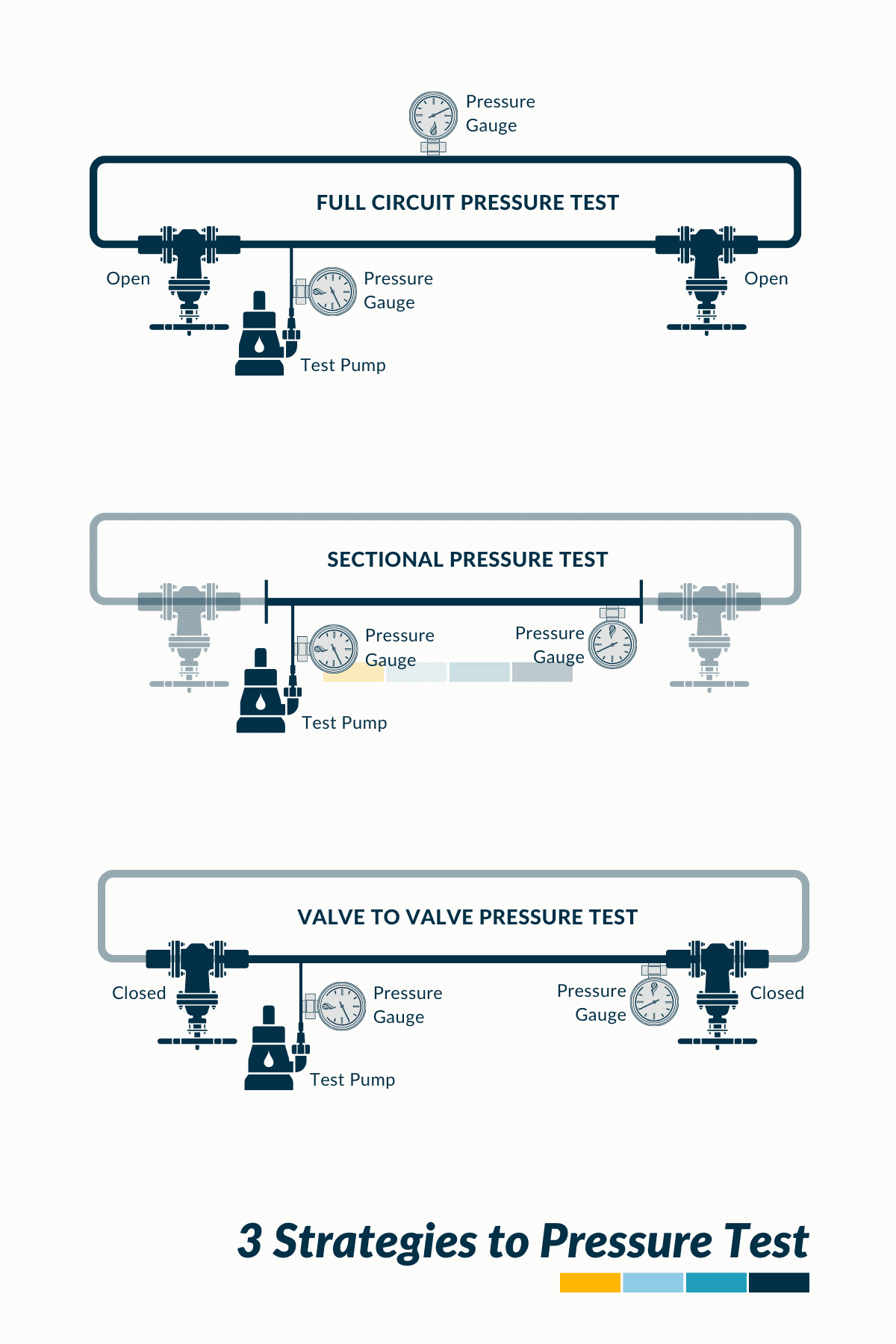
| Total System Pressure | Total System Pressure' will cover all pipework, joints, equipment, etc for a complete system. This is usually the best and quickest way to test, but subject to the system size and configuration. Commonly completed after the Pipework Flushing and Cleaning Stage of the Onsite Commisisoning Process. |
| Sectional Test | Sectional Pressure Testing' will involve splitting the complete pipework/equipment into various smaller sections by blanking off each section. This method is usually used on larger projects where testing the complete system at once is not feasible. Usually completed before water flushing etc. |
| Valve to Valve Test | Valve to Valve Testing' is used similar to a sectional test, but in this case, the valves are used as the blanks. Testing will go to the back of the valves or through the valves. As the valve to valve testing is completed the whole system will be covered |
If you would like to read more on pipework flushing and cleaning, see our article | 'FLUSHING & CLEANING | Pipework Systems Overview.'
🟩 Types Of Systems And Materials Testing Covers
Within the construction industry, pressure testing can be used on the following types of systems and types of materials:
| System Type | Common Materials |
|---|---|
| Incoming mains water | HDPE |
| Domestic water supply | Copper |
| Hot water system | Copper |
| Grey water | PVC |
| Flush water | Copper |
| Irrigation systems | Galvanized |
| Condenser water | Galvanized |
| Chilled water | Steel / Copper |
| Heating system | Steel / Copper |
| Sprinkler system | Steel |
| Hose reel system | Steel |
🟩 How Does Hydraulic Pressure Testing Work?
Pressure testing involves filling the pipework system or component with water and then pressurizing it to a level that exceeds its normal operating/design pressure, testing its integrity.
The pressure is usually created using a hand pump or compressor in a larger system.
As the pressure inside the pipework/system increases, it starts to exert a ‘hydraulic force’ on the internal walls of the pipework and any joints or fittings that are connected and installed.
If there are any weak points in the system, such as a faulty joint or a crack in a pipe, the hydraulic pressure will cause the system to fail at that point, either by causing a leak or by causing the system to rupture – resulting in a failed test. If there are no weak points, the pressure will remain in line with the pressure that was created.
Overall, hydraulic pressure testing is a way to ensure that pipework systems are safe and reliable by subjecting them to high levels of pressure to test their strength and integrity.
![Pneumatic & Hydrostatic Pressure Testing Method Statement Template [MS Word]](https://constructandcommission.com/wp-content/uploads/2023/03/003f.webp)
OPEN TEMPLATE of our PNEUMATIC & HYDRAULIC PRESSURE TESTING Method Statement including INSTRUCTIONS, that can be downloaded allowing editing and clean exporting for your project/company use.
All as per the format and layout are shown in the sample document, at the end of this article.
🟩 What Testing Pressure Should Be Used?
Similar to the above, this will depend on the type of system and project requirements; as an example, if we are looking at chilled water, condenser water, mains water, or heating hydraulic system that has been installed using carbon steel, copper or galvanized Pipework the expected pressure used will be 1.5 times the design pressure, according to BESA – see table in next section.
⚠️ As noted, check the project specifications – if nothing is indicated, then 1 hour should suffice, and BESA can be referenced as an industry standard.
🚀 BESA – Building Engineering Services Association | Document TR6 Guide to Good Practice – Site Pressure Testing of Pipework. [BESA Publication | Details of your selected Publication (thebesa.com)]
We have added a Pressure Conversion Table to the site see 'PRESSURE CONVERSION TABLE | Bar, Pa, Kpa & Psi' if want to read more
🟩 How Long Should Pressure Testing Take?
This will depend on the type of system and project requirements; as an example, if we are looking at chilled water, condenser water, mains water, or a heating hydraulic system that has been installed using carbon steel, copper, or galvanized Pipework, the time period required according to BESA is for the system to hold steady for 1 hour.
⚠️ As noted, check the project specifications – if nothing is stated, then 1 hour should suffice, and BESA can be referenced as an industry standard.
🟩 Reference Table – Pressure, Time, and Tolerances
For most systems requiring a hydrostatic test, it would be in line with the below table/graphic that details the requirements of a hydrostatic test, including the length of time for testing and pass/fail tolerances.
Testing Tolerances provide clear direction as to what the allowable error within the testing results will be acceptable and is represented by a +/- value. If the testing result falls within the tolerances, it will be deemed a ✅ PASS; if it does not, it will be deemed a ❌ FAIL.
If a result is ‘out of tolerance,’ then a retest must be completed.
As shown in the table below, testing tolerance for a general water pressure test following BESA would be 0% drop or gain.
⚠️ This table is provided as an example, and for your specific requirements, the specifications and contract documentation should be checked.
| System | Hydrostatic Testing | Medium Used | Testing Pressure | Duration | Tolerance |
|---|---|---|---|---|---|
| Chilled Water System | Yes | Water | 1.5x working Pressure | 1 hour | +/-0% |
| Condenser Water System | Yes | Water | 1.5x working Pressure | 1 hour | +/-0% |
| Sea Water System | Yes | Water | 1.5x working Pressure | 1 hour | +/-0% |
| LPHW Heating System | Yes | Water | 1.5x working Pressure | 1 hour | +/-0% |
| MPHW Heating System | Yes | Water | 1.5x working Pressure | 1 hour | +/-0% |
| HPHW Heating System | Yes | Water | 1.5x working Pressure | 1 hour | +/-0% |
| Condensate System | Yes | Water | 1.5x working Pressure | 1 hour | +/-0% |
| Cold Water Mains System | Yes | Water | 1.5x working Pressure | 1 hour | +/-0% |
| Flushing Water System | Yes | Water | 1.5x working Pressure | 1 hour | +/-0% |
*See our pneumatic pressure testing article for further information
Included below are links to some of our other articles that you may also find useful:

Testing of Centrifugal Pumps, CENTRIFUGAL PUMP | Commissioning and Alignment
🟩 Pressure Testing Guidelines & Regulations
🟧 Guidelines
Although pressure testing is seen as a quick basic test that anyone can complete with a hand pump and a calibrated gauge, there are currently four guidelines that can be referred to that would allow the testing to be specified properly.
- BESA TR/6 Site Pressure Testing of Pipework [UK developed]
- ASME Power Piping Code B31.1 [USA developed]
- ASME Process Piping Code B31.3 [USA developed]
- ASME Code for Pressure Piping B31.9 [USA developed]
These Guidelines are similar in process and outcome, but in our opinion – BESA provides better information on the requirements and methods of testing. Especially for different types of pipework.
🟧 Regulations
Within the United Kingdom, pressure testing pipework regulations are covered by ‘the Provision and Use of Work Equipment Regulations 1998 (PUWER)’.
These should be referenced to understand your responsibilities as an employer when carrying out these types of activities.
🟩 Hydrostatic Pressure Testing Calculations
To understand the ‘Hydraulic Testing Pressure’ requirement that the system needs to be exposed to, we first need to calculate the following:
- System Static Pressure
- System Pump Pressure
- Maximum Working System Pressure
🟧 System Static Pressure Calculation
System Static Pressure [SSP] refers to the pressure exerted by a hydraulic water column when it is not in operation and is influenced by a couple of factors:
- Type of Fluid
- Density of Fluid
- Height of the System
If the static pressure is not provided within the design documents, it can be calculated by using the following equation:
p = ρ × g × h + p0
Where:
p = hydrostatic pressure [Bar, kpa, psi]
ρ = density of the fluid [kg/m³, slugs/ft³]
g = gravitational acceleration [9.81m/s²] [32.174 ft/s²]
h = height of the water column [m] [ft]
p0 = external pressure [101.33 kPa atmospheric]
🚀 System Static Pressure Calculation Example
To find the static pressure of a chilled water system using pure water, with a total vertical water column height of ’10’m [‘32.81’ft], the hydrostatic pressure would be:
p = ρ × g × h + p0
p = 1000kg/m³ × 9.81m/s² × 10m + 101.33
p = 98.2kpa, 0.982bar, 14.24psi
Below is a table showing different static pressures for various water column heights:
| 'x'm | 'x'ft | bar | kpa | psi |
|---|---|---|---|---|
| 1 | 3.28 | 0.10 | 9.91 | 1.44 |
| 2 | 6.56 | 0.20 | 19.72 | 2.86 |
| 3 | 9.84 | 0.30 | 29.53 | 4.28 |
| 4 | 13.12 | 0.39 | 39.34 | 5.71 |
| 5 | 16.40 | 0.49 | 49.15 | 7.13 |
| 10 | 32.81 | 0.98 | 98.20 | 14.24 |
| 15 | 49.21 | 1.47 | 147.25 | 21.36 |
| 20 | 65.62 | 1.96 | 196.30 | 28.47 |
| 25 | 82.02 | 2.45 | 245.35 | 35.59 |
| 30 | 98.43 | 2.94 | 294.40 | 42.70 |
| 35 | 114.83 | 3.43 | 343.45 | 49.81 |
| 40 | 131.23 | 3.93 | 392.50 | 56.93 |
| 45 | 147.64 | 4.42 | 441.55 | 64.04 |
| 50 | 164.04 | 4.91 | 490.60 | 71.16 |
| 100 | 328.08 | 9.81 | 981.10 | 142.30 |
🟧 Maximum Working System Pressure Calculation
This will calculate the total pressure that the overall system will experience when in operation; it can be calculated by using the following equation:
MWSP = SSP + SPP
Where:
MWSP = Maximum Working System Pressure [Bar, kpa, psi]
SSP = System Static Pressure [Bar, kpa, psi]
SPP = System Pump Pressure [Bar, kpa, psi]
Once this has been understood, the Hydraulic Testing Pressure can be worked out, providing the pressure to which the system is to be pressurized.
🚀 System Maximum Working Pressure Calculation Example
A chilled water system has a System Static Pressure [SSP] of 98.2kpa and a System Pump Pressure [SPP] of 147kpa. What is the Maximum System Working Pressure [MWSP] in the system, expressed in bar, kPa, and psi?
MWSP = SSP + SPP
MWSP = 147 kpa + 98.2 kpa
MWSP = 245 kPa, 2.45 bar, 35.6 psi.
🟧 Hydraulic Testing Pressure Calculation
To calculate the actual testing pressure that the system will be exposed to, use the following:
HTP = MWSP x 1.5
Where:
HTP = Hydraulic Testing Pressure
MWSP = Maximum Working System Pressure
1.5 = as per BESA TR/6
🚀 Hydraulic Testing Pressure Calculation Example
A chilled water system has a Maximum Working System Pressure [MWSP] of 245kpa. What is the Hydraulic Testing Pressure [HTP] that the system should be tested too in Bar, kPa, and psi?
HTP = 245 kpa x 1.5
HTP = 367.5 kpa, 3.67 bar, 53.22 psi
🟩 Reference Chart – Bar to PSI to kPa Chart
Below is a chart showing the conversion between the Bar, kPa, and psi pressure units.
For additional information and conversions up to 50 bar, see our article | '***'
| Bar | Pa | kPa | Psi |
|---|---|---|---|
| 0.25 | 25000 | 25 | 3.625 |
| 0.50 | 50000 | 50 | 7.25 |
| 0.75 | 75000 | 75 | 10.875 |
| 1.00 | 100000 | 100 | 14.5 |
| 1.25 | 125000 | 125 | 18.125 |
| 1.50 | 150000 | 150 | 21.75 |
| 1.75 | 175000 | 175 | 25.375 |
| 2.00 | 200000 | 200 | 29 |
| 2.25 | 225000 | 225 | 32.625 |
| 2.50 | 250000 | 250 | 36.25 |
| 2.75 | 275000 | 275 | 39.875 |
| 3.00 | 300000 | 300 | 43.5 |
| 3.25 | 325000 | 325 | 47.125 |
| 3.50 | 350000 | 350 | 50.75 |
| 3.75 | 375000 | 375 | 54.375 |
| 4.00 | 400000 | 400 | 58 |
| 4.25 | 425000 | 425 | 61.625 |
| 4.50 | 450000 | 450 | 65.25 |
| 4.75 | 475000 | 475 | 68.875 |
| 5.00 | 500000 | 500 | 72.5 |
| 5.25 | 525000 | 525 | 76.125 |
| 5.50 | 550000 | 550 | 79.75 |
| 5.75 | 575000 | 575 | 83.375 |
| 6.00 | 600000 | 600 | 87 |
| 6.25 | 625000 | 625 | 90.625 |
| 6.50 | 650000 | 650 | 94.25 |
| 6.75 | 675000 | 675 | 97.875 |
| 7.00 | 700000 | 700 | 101.5 |
| 7.25 | 725000 | 725 | 105.125 |
| 7.50 | 750000 | 750 | 108.75 |
| 7.75 | 775000 | 775 | 112.375 |
| 8.00 | 800000 | 800 | 116 |
| 8.25 | 825000 | 825 | 119.625 |
| 8.50 | 850000 | 850 | 123.25 |
| 8.75 | 875000 | 875 | 126.875 |
| 9.00 | 900000 | 900 | 130.5 |
| 9.25 | 925000 | 925 | 134.125 |
| 9.50 | 950000 | 950 | 137.75 |
| 9.75 | 975000 | 975 | 141.375 |
| 10.00 | 1000000 | 1000 | 145 |
🟩 How to check hydraulic pressure
🟧 New System
If a new system is to be installed, the hydraulic pressure would be provided by the HVAC designer of the system; note that this should include the pump operating pressure.
Where this information is not included within the design documents, then an RFI [request for information] should be raised.
We have written an article on the RFI process; see | [RFI] REQUEST FOR INFORMATION | What is it in Construction with Templates
🟧 Existing System
Where a system exists without design data, the system’s hydraulic pressure can be checked via instruments and pressure sensors.
If none are installed, a temporary calibrated pressure gauge at the lower part of the system can be useful.
Here are some steps to do this:
🟨 Step 1 – Locate a pressure tap or test port
A pressure tap or test port is a point in the system where a temporary instrument can be installed so that a pressure measurement can be taken; there is usually an isolation valve that can be used to open and close the system to the gauge.
They are usually located near a pump.
🟨 Step 2 – Attach a temporary pressure gauge or sensor
Attach the temporary pressure gauge or sensor to the pressure tap or test port. Ensure the connections are tight and secure, checking for leaks.
🟨 Step 3 – Open the isolation valve
Open the isolation valve that controls the flow to the pressure tap or test port. This will allow the fluid to flow through the gauge or sensor.
🟨 Step 4 – Check the pressure reading
Check the pressure reading on the gauge or sensor.
🟨 Step 5 – Record the reading
Record and document the pressure reading for future reference and use when determining the hydraulic testing pressure.
🟩 Testing Equipment to Be Used [PDF]
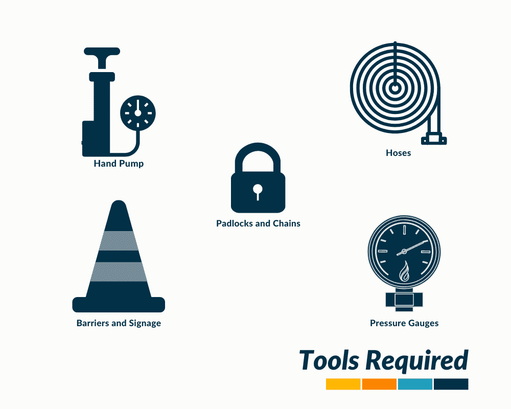
The following equipment will be utilized during the Hydraulic Pressure Testing works.
- Hand Pump: A pump that generates the required hydraulic pressure within the system.
- Hoses: these are flexible tubes/pipes, rated at the correct pressure, connected from the pump to the system under test. They can also be used for looping and connecting other systems.
- Calibrated Pressure Gauges: used to measure and monitor the pressure within the system that is under test.
- Pad Locks and Chains: to lock off valves or other system components to ensure they cannot be inadvertently opened during the test.
🟩 Pressure Testing Safety Checklist
A few requirements are needed before starting the work to ensure the testing is completed safely.
To download these checklists [MS Word / PDF], click on the button below to be taken to our shop:
🟧 Personal Protective Equipment [PPE]
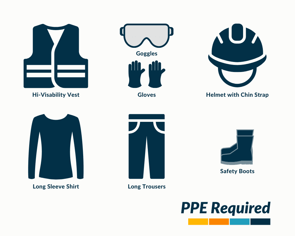
Personal Protective Equipment [PPE] refers to any equipment or clothing worn by anyone involved in the works to protect themselves from the hazards they will be exposed to.
Each project should be evaluated for its specific risks, but in general, the PPE that will be worn would be:
| Type | Protecting | Notes |
|---|---|---|
| Hi-Visability Vest | Designed to make the wearer more visible to others, typically in situations where visibility is low, such as in dimly lit areas. | |
| Goggles | Eyes | Provides protection for the eyes against impact, debris, chemicals, and other hazards that may be present during the works. |
| Gloves | Hands | Worn to protect the hands from potential hazards such as cuts, burns, and chemical exposure. |
| Helmet | Head | Protects the head from falling objects, bumps, and other potential hazards that may be present during the works. |
| Chin Strap | An adjustable strap that attaches to a helmet and is worn under the chin to keep the helmet securely in place and prevent it from falling off in the event of an impact. | |
| Long Sleeve Shirt | Arms | Worn to cover the arms and torso, providing protection against cuts, scrapes, and other potential hazards. |
| Long Trousers | Legs | Provides leg protection against cuts, scrapes, and other potential hazards. |
| Safety Boots | Toes/Feet | Designed to provide protection to the feet against potential hazards such as falling objects, sharp debris, and slippery surfaces. They should typically have reinforced toes and non-slip soles for added protection. |
🟧 Site Safety Equipment
Where PPE is worn to protect those completing or involved with the tasks, site safety equipment is used to allow them to carry out the work safely.
Items of equipment that could be used would be:
| Type | Notes |
|---|---|
| Safety Signage | Safety signage is used to warn people of potential hazards, provide information about safe practices, and direct individuals to safety equipment or exits. These signs are typically made of durable materials and display symbols or text that are universally recognized. |
| Barriers/Cones | Barriers and cones are used to cordon off areas where the works are being carried out or where there are potential hazards. They are used to prevent people from entering the areas and to ensure that individuals remain at a safe distance. |
| Spill Kits | Used to contain and clean up spills of liquids. These kits contain materials such as absorbent pads, booms, and gloves, and are designed to be easily accessible in case of an emergency. |
| Access Platforms | Provides a safe and stable platform for workers to carry out their tasks at height. Covering items such as scaffolding, mobile elevating work platforms [MEWPs], and ladders [where safe] |
| Fall Protection | Fall protection equipment is used to prevent workers from falling from height. This can include items such as safety harnesses, anchor points, and safety nets. Fall protection equipment is often required by law when working at height, and should be inspected regularly to ensure that it is in good condition. |
🟩 Hydrostatic Pressure Testing Method
Below are the steps necessary to deliver a successful pressure test.
🟧 Step 1 – Complete General Pre-Requisites Checks
The checks, as detailed below, should be completed to ensure that everything is set up for the testing to commence.
| Ref | Details | Notes |
|---|---|---|
| 1 | All Technical / Material Submissions Status A | |
| 2 | All Drawings of System [Layouts & Schematics] Status A and fully marked-up showing clearly the testing areas and testing numbers, being proved via a visual inspection. | Where a different status is shown the following will be allowed: Status B - Testing can proceed as long as comments have been addressed and do not affect the testing. Status C & D - Testing will not proceed |
| 3 | Testing Method Statement reviewed and provided a Status A | Where a different status is shown the following will be allowed: Status B - Testing can proceed as long as comments have been addressed and do not affect the testing. Status C & D - Testing will not proceed |
| 4 | All Delivery Records Available for Inspection | |
| 5 | All Installation Inspection Records Available | For Inspection showing systems to be tested have been inspected by the Resident Engineering Team and, accepted as being installed in line with the project requirements. Where not available testing will not be allowed to commence. |
| 6 | All Permits are in place as noted in the 'Permit to Work' Section & system set up for testing, padlocks, protections, signage, etc. | Where not available testing will not be allowed to commence. |
| 7 | Items of equipment that may be affected by the higher pressures are isolated or removed and replaced with spool pieces. | Where not testing will not be allowed to commence. |
| 8 | All pipework fittings and equipment is rated for the pressure testing requirement. | Equipment, Hoses, Valves, Control Valves, Connections, Gaskets. This is can be an issue in high-rise buildings. |
| 9 | Calibration Certificates are available for all instruments and equipment and are within date. | |
| 10 | Pressure Gauge is installed at the lowest point and highest/furthest point of the system with a display/range applicable to the testing pressure. | If not they will need to be relocated or replaced. |
| 11 | If a pump is being used, a consistent water source is available to feed it with water and is connected to the system at the lowest point. | If not there will need to be. |
| 12 | Power is available if a pump/compressor is being used. | |
| 13 | All pipework joints are exposed, i.e not insulated to allow for observing of the system. | |
| 14 | System filled and fully vented free of air. | Automatic & Manual Air Vents will need to be manually isolated after venting. |
| 15 | System set up in line with any strategies, valves open/closed / blanks installed, etc. | |
| 16 | Hoses installed at low-level drain cocks and run to drain. | Used in case of a leak in the system and will allow pressure to be reduced quickly |
| 17 | Operative and Engineers fully trained and where required hold a current relevant certificate to complete the works. |
🟧 Step 2 – Pipework Installation Checklist/Inspection Record
Before the testing and commissioning phase takes place, the following will be checked.
| Ref | Inspection/Task |
|---|---|
| 1 | Pipework is installed in line with the project drawings [size, location]. |
| 2 | Piping is free to expand and contract without noise or damage to hangers, joints, or the building. |
| 3 | Seismic restraints, where required, installed. |
| 4 | Pipework does not put undue stress on equipment, where connected and is bracketed to support itself. |
| 5 | All piping supports and hangers meet criteria set out in the specifications. |
| 6 | Piping is installed with sufficient pitch and arranged in a manner to ensure drainage and venting of the entire system. |
| 7 | Manual air vents are provided at high points in closed water systems. |
| 8 | Ensure all gaskets are installed and sealed. |
| 9 | Ensure that all bolts are installed as per manufacturer's instructions. |
| 10 | Any nipples installed are made of the same material as the pipe. |
| 11 | Any connections between copper and steel pipes are made with dielectric fittings. |
| 12 | A union is provided ahead of each screwed valve, trap, or strainer, and on each side of each piece of equipment and whatever needed to dismantle piping. |
| 13 | Any changes in pipe sizes are made with the proper size reducing fittings, reducing fittings, reducing elbow, or reducing tees. Bushings are not allowed. |
| 14 | All fittings meet specification requirements. |
| 15 | All fittings and ancillaries are rated correctly and inline with the pressure of the system. |
| 16 | All equipment requiring maintenance is accessible (valves, junction boxes, etc.). |
| 17 | Piping does not block access to equipment that is part of this system or another system (e.g., air terminal units). |
| 18 | Drain valves are provided at all low points in hose bib piping to facilitate seasonal draining. |
| 19 | All valves [isolation, commissioning, non-return etc] are installed as per the drawings |
| 20 | All strainers are installed as per the drawings and baskets are clean. |
| 21 | Pipework is insulated as per the specification and vapor sealed where required. |
| 22 | Piping is installed in a manner to ensure that insulation will not contact adjacent surfaces. |
| 23 | Any pipe openings are temporarily sealed to maintain piping system cleanliness. |
| 24 | All components including valves and controls are labeled in line with the project naming convention. |
| 25 | Instruments, flow meters, energy meters, and commissioning stations have been installed in line with the manufacturer's requirements and correct direction. This includes distances from turbulent flows etc. |
| 26 | All pressure gauges installed, and display scale as per design requirements. |
| 27 | Pipework has been magnetic weld tested, where specified. |
| 28 | Pipework has been ultrasonic weld tested, where specified. |
| 29 | System has been filled and bled with air removed. |
![General Pipework Pre-Commissioning Checklist Template [MS Word] + [MS Excel]](https://constructandcommission.com/wp-content/uploads/2023/03/049i.webp)
Here is our open copy [MS Word] of the GENERAL PIPEWORK Pre-Functional Checklist, for making life a little easier...
We have also recently formatted this checklist to [MS Excel] and included it as a Bonus for FREE.
So get an MS Word & MS Excel for the same price.
Once the above table has been verified and agreed upon, the Hydraulic Pressure Test can be commenced using the steps below, with the hand pump, valves, and gauges connected:
🟧 Step 3 – Raising the System Pressure
Raise the system pressure by opening the valves to the hand pump, then slowly raise the water pressure within the system in 1 bar / 14.5 psi increments.
Stop when the gauge reading meets the required testing pressure.
🟧 Step 4 – Allow the System to Stabilise
Once the testing pressure is reached and verified, shut off the valves at the system connected to the compressor and allow the system to settle for 10 minutes,
If there is a drop in pressure during the 10 minutes, this could be due to the system settling; use the hand pump to top-up the system, and ensure the valves are opened before pumping and closed after completing [this will be the only time a top-up is allowed].
🟧 Step 5 – Confirm System Is Stable
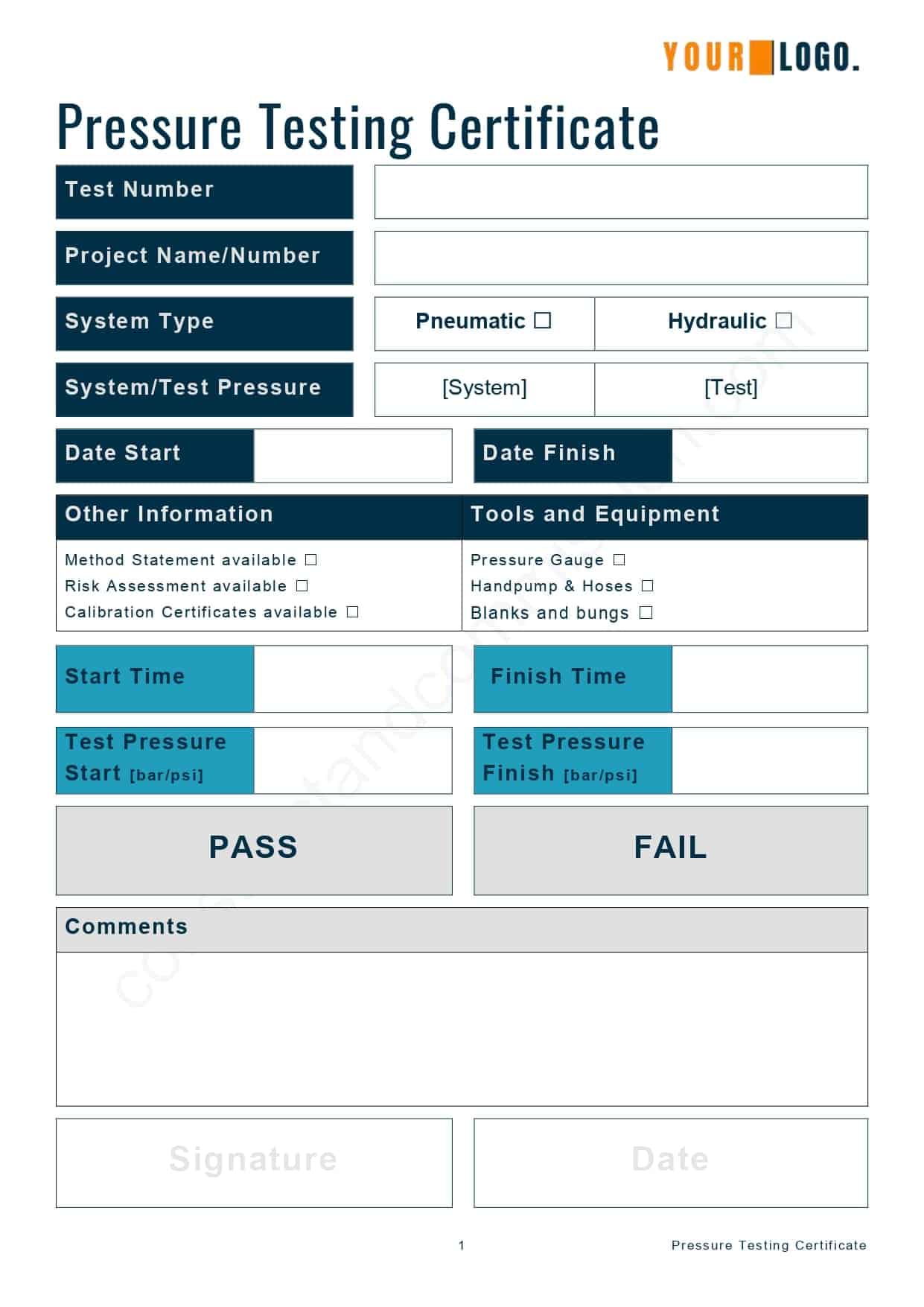
Once the system is stable, fill out the pressure testing certificate by documenting the required information.
✅ The testing time will now start.
Here is a ‘Hydrostatic Pressure Test Certificate Template’ that can be downloaded in PDF or MS Word.
⬜ Hydraulic Pressure Testing Certificate Template
The following certificate can be emailed to you for use in your works and reports from our shop; click the ‘Download’ button if you want a copy.
🟧 Step 6 – Testing Started
Once Step 5 has been completed and verified, ensure that the testing pressure is held for the period noted in the contract documents and in line with the expected tolerances.
During the testing time, check the system and gauges for any signs of leakage or loss of pressure.
🟧 Step 7 – Completion Of Testing
✅ If no pressure loss is noted over the required time frame, then the test can be completed and a Pass provided.
Finalize pressure testing certificate and file.
❌ If leaks or pressure loss are outside of the tolerances noted, they should be investigated and addressed.
Failure of water tightness within a system will usually be noted at flanges, joints, or connections to equipment.
Once all remedial works have been completed, retesting will be conducted until the system passes.
Finalize pressure testing certificate and file.
🟧 Step 8 – Depressurize The System
Once everything has been confirmed as complete, safely depressurize the system by draining some water off to drain or into a bucket.
🟧 Step 9 – Removal of Testing Equipment
When the testing has been confirmed as complete and passed, the hand pump, gauges, and temporary valves/hoses should be removed, with any equipment checked or reinstalled to ensure normal status.
⬜ Hydraulic Pressure Testing Method Statement Template
Here is an example of a pressure testing document, including hydrostatic and pneumatic, that can be purchased and downloaded in our shop; click the ‘Buy Now’ button.
⬛ Hydrostatic Testing Questions and Answers
⬜ Can Hydrostatic Testing Cause Damage To A System?.
Yes, hydrostatic pressure testing a system can, if not completed by experienced operatives and engineers who fully understand the requirements, cause damage. Sometimes catastrophic, life-threatening, and extremely expensive.
⬜ What is Maximum Allowable Hydraulic Testing Pressure
The maximum allowable hydraulic testing pressure is the maximum pressure a hydraulic system, pipeline, or component can be subjected to during a hydraulic pressure test without experiencing permanent damage or failure.
Refer to the manufacturer’s data sheets/operation manuals to understand this.
⬜ Difference Between Hydro Test And Hydrostatic
Hydro testing refers to any test that uses water or another liquid to verify the integrity of a system or component. This can include tests using water, oil, or other fluids and can be done using either a hydrostatic or pneumatic method.
Hydrostatic testing is a specific type of hydro test that involves filling the system or component with water and pressurizing it to a specified level. The pressure is held for a set amount of time to ensure no leaks or failures. This is a common method for testing pipelines, vessels, and other pressure-containing components.
⬜ Pressure Testing With Air vs. Water
There are several reasons why we might choose to conduct a Pneumatic [Air] Pressure Test over a hydrostatic test, for example:
- the system or vessel cannot be filled with liquid due to design or operational constraints,
- the system or vessel is being tested for leaks or other issues that may not be detectable with a hydrostatic test.
- The test requires a higher pressure than can be achieved with water or another liquid.
It’s important to note that a pneumatic pressure test is typically more dangerous than a hydrostatic test; proper safety precautions must be taken to prevent injury or damage to equipment.
⬜ Can You Use The System Pressure Gauges For Reading
Generally, you should not use the system gauges as they tend not to be calibrated. All gauges should be fully calibrated with accompanying certificates when conducting the testing and ensuring accuracy.
⬛ Related Articles
CRAH UNIT | Pre-Functional CheckList
CENTRIFUGAL PUMP | Pre-Commissioning Checklist
WATER COOLED CHILLER | Pre-Commissioning Checklist
CRAH UNITS | What are they?
LOW PRESSURE PNEUMATIC TEST | Prior to Hydraulic Testing
FAN COIL UNIT | Pre-Commissioning Checklist