Completing the correct pump commissioning and alignment activities ensure that the equipment installed is operating at its optimum efficiency and is fully in line with the project design parameters and manufacturers technical datasheets; the following testing should be completed and, where specified, witnessed:
- Alignment Check
- Rotation Check
- Electrical Emergency Stop
- Closed Head Test
- Electrical Measurements
- Full Flow Test
The below information will step through each stage of testing and commissioning sequence for a pump expanding upon the requirements, including what tools should be used, and tolerances, etc.
If would like to understand how to write a method statement check out our article HOW TO WRITE A TESTING AND COMMISSIONING METHOD STATEMENT
General information
Pumps come in various configurations and sizes, the below information is based upon the most basic type that we come across, ‘Centrifugal Pumps’, that are used in commercial and industrial chilled water and heating systems.
It is assumed that the pump motor megger/insulation testing has been completed prior to the mechanical testing taking place. If it has not then this should be conducted prior to the below.
Pump Factory Testing
It should be noted that, unless specified and requested within the order to the supplier/manufacturer, pumps are not usually factory tested.
![Centrifugal Pump Functional Testing Template Method Statement [MS Word]](https://constructandcommission.com/wp-content/uploads/2022/01/050-3.webp)
Competent Persons
All works should be completed by an experienced and competent person, who understands the systems and has the correct qualifications.
Pump Commissioning Checklist
Prior to the pumps being functionally tested, they should be inspected to ensure that the commissioning works will not be impacted.
To allow this a detailed Pump Commissioning Checklist should be used as a reference to inspect and tick off for record.
We have written an article Downloadable PUMP Commissioning Checklist to cover these works, detailing the inspections that should be completed from delivery to pre-commissioning, ensuring the product quality. quality of installation, and allowing the commissioning activities to start
Testing Tolerances
In order for the testing to be deemed successful by the commissioning team, there will be some tolerances that we will need to adhere to and analyze the reported and measured information against.
| Mains [flow from [pumps] | Design +10%/-0% |
| Pump Alignment | As per manufacturers literature |
Testing Tools
The following tools will usually be required with the relevant calibration certification:
| Mechanical Tools | Electrical Tools |
| Water Manometer | Clamp Ammeter |
| Tachometer | Multimeter |
| Pressure Gauge | |
| Pump Alignment Tools [Straight Edge, Dials, Lasers] | |
| Pump Curve for the pump under test |
Obtain Pump/Motor Information:
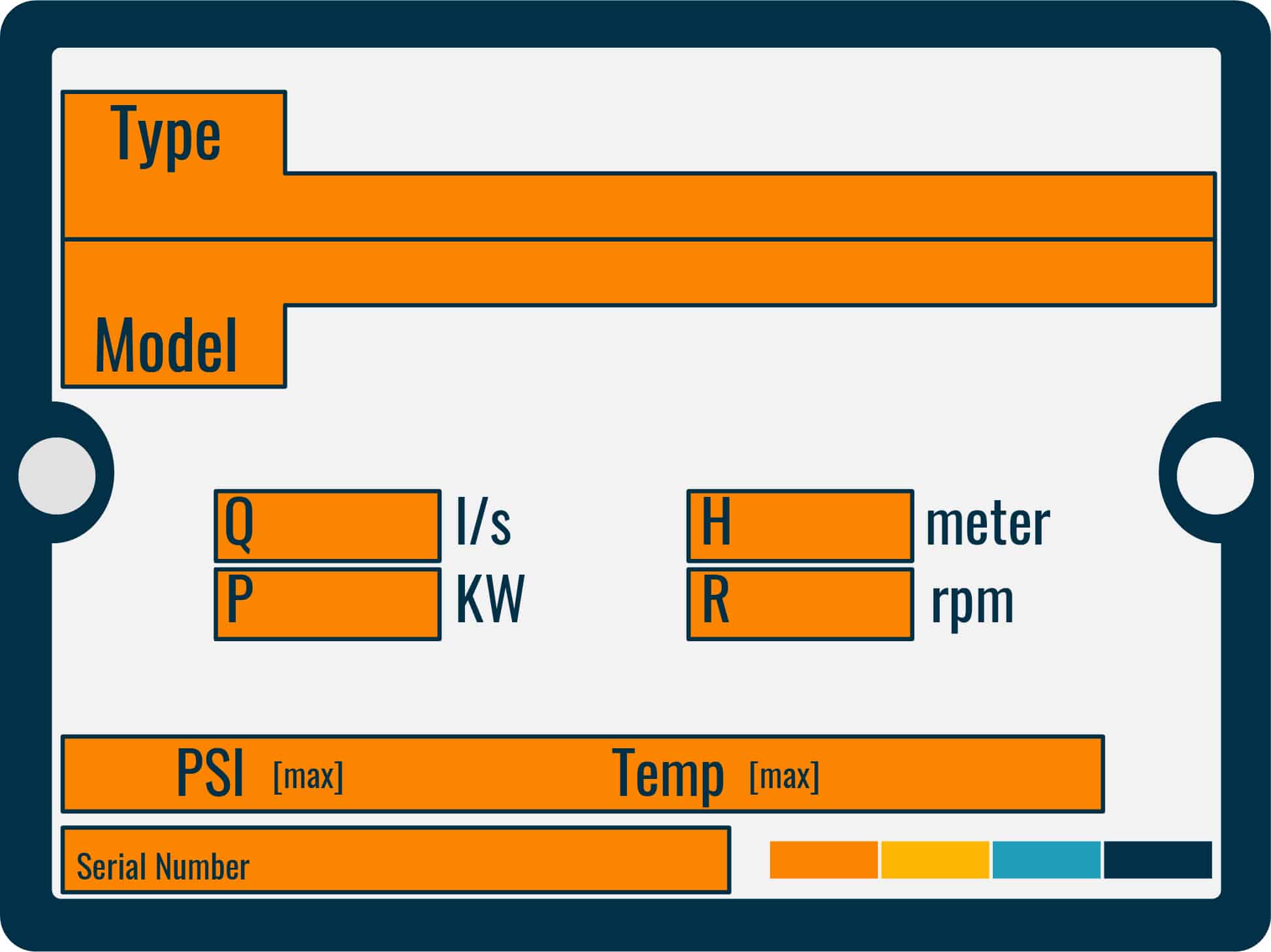
Prior to testing ensure all the details are taken and documented, from the pump and motor:
- Manufacturer
- Type
- Model
- Serial Number
- Impeller Size
- Motor [KW]
- RPM
- Overload Setting [amps]
- Full Load Current [amps]
Test 1: Pump Alignment
Pump alignment is required to be completed prior to the equipment being run for an extended time and will ensure that:
- The equipment is installed and meets the manufacturers requirements
- There is no stress on the shafts
- Vibration is reduced

The alignment should be completed by a competent person, usually, the pump manufacturer, with a full report and documentation provided that can be included within the pump commissioning report/final documentation.
There are generally 3 ways to complete and align pumps:
- Straight Edge Alignment
- Dial Indicator Alignment
- Laser Alignment
![Flushing & Chemical Cleaning Method Statement [MS Word]](https://constructandcommission.com/wp-content/uploads/2022/04/000-PH-Document-Graphic-Sell-3.webp)
Here is our Open Copy of our Flushing and Chemical Cleaning Method Statement in MS Word. With instructions
Straight Edge Alignment
This is the most basic and least accurate method, one that should be avoided as there are much better more accurate methods that will help the overall wear and tear on the pumps/maintenance costs
A straight edge will be placed on the pump and coupling, with the components being visually inspected for alignment by the eye. The upper and lower coupling gap is measured with a feeler gauge.
With the tolerances specified by the manufacturer, the human eye may not see the difference.
Dial Indicator Alignment
The dial method can cover techniques such as:
- Cross Dial
- Reverse Dial
- Rim & Face
The cross dial method will take measurements motor shaft to pump shaft by reading two indicators mounted 180 degrees apart,
The reverse dial method takes measurements from indicators in the same plane as the shafts.
If there is a situation where only 1 shaft can be rotated then the rim and face dial method will usually be used.
Laser Alignment
The most accurate of the three methods and one that would be suggested, as manufacturers’ tolerances are usually very tight.
The lasers are placed on the motor and pump shafts with data and information being relayed back to a computer that will provide instructions and data on how to align and adjust the shafts.
Alignment Method Comparison Table
| Type | Skill Required | Accuracy | Time to Complete | Cost of Tools |
| Straight Edge | Low | Low | Short | $ |
| Dial Indicator | High | Medium | Long | $$ |
| Laser | Medium | High | Short | $$$ |
Test 2: Rotation Check
A direction of rotation check is needed to ensure that the pump impeller spins in either its designed clockwise direction or counter-clockwise direction.
Ensure the pump is run for as short a time as possible [10 seconds max].
Complete the following steps:
- Turn the pump on
- Check pressure gauges to ensure water is flowing correctly
- Turn pump off
Test 3: Emergency Stop Test
In order to ensure that the pump will stop immediately under emergency conditions, even during the testing, the emergency stop button protection device should be checked for operation.

Complete the following steps:
- Turn the pump on
- Allow pump to run for a few seconds
- Hit/press emergency stop button
- Pump stops
Test 4: Conduct a Closed Head/Dead Head Test
This test is conducted to ensure that the pump is operating correctly and that there are no potential issues lurking within the pump itself.
It should be noted that this is a closed head test for a Centrifugal Pump, and the time of running the pump should be kept to a few seconds only so as not to damage it.
Complete the following steps:
- Pump off
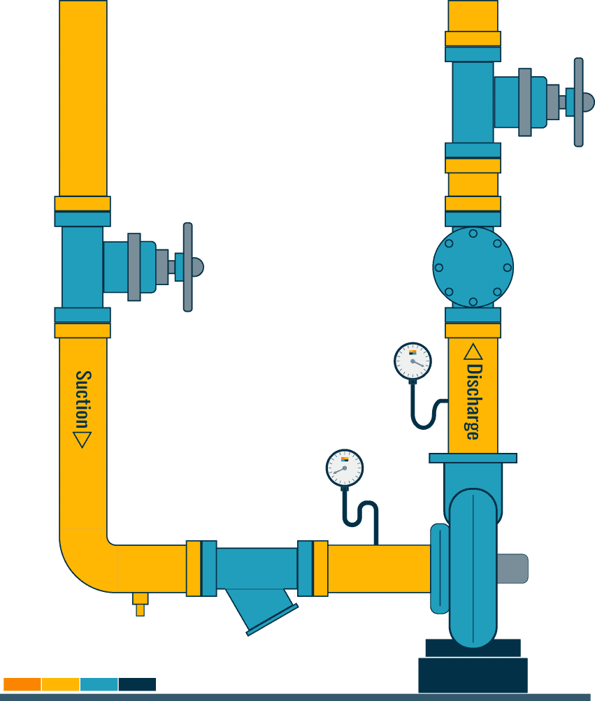
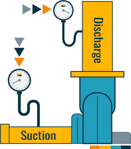
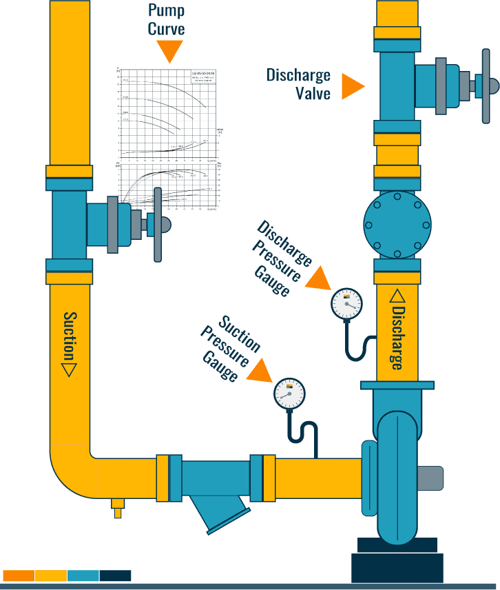
- Attach calibrated pressure gauges to the discharge & suction side of the pump [usually replace the existing gauges temporarily]
- Get the correct pump curve related to the model testing and pen to note the details required
- Ensure that the seals for the pump are rated for a dead head test
- Turn pump on
- Slowly close the pump discharge valve 100%
- Once fully closed, quickly read and note the discharge and suction pressures at the gauges [few seconds]
- Turn pump off
- Open discharge valve
So that is the readings taken, now we need to review the information obtained against the manufacturer’s pump curve to ensure there are no issues.
Test 4a: Calculate differential pressure
With the data obtained for the discharge and suction pressure at the gauges, calculate the differential pressure based upon the following:
- If the suction pressure is positive
- [-] minus from the discharge pressure
- If the suction pressure is negative
- [+] add it to the discharge pressure
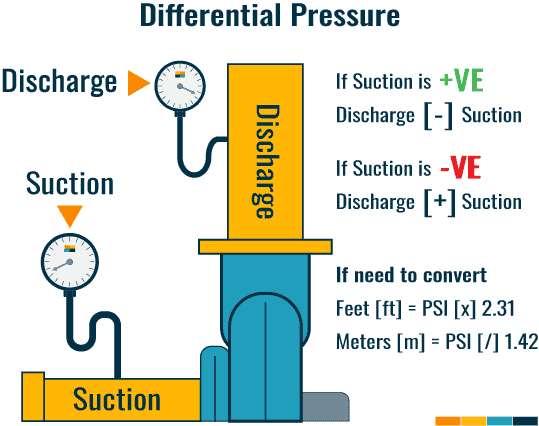
The result will usually be in PSI [pounds per square inch].
This will need to be converted to what the pump head is measured in, usually Feet [ft] or Meters [m].
To do this use the following calculation:
Feet [ft] = PSI x 2.31
Meters [m] = PSI/1.42
Test 4b: Plot the pump curve
Once we have obtained the differential pressure and calculated it into the pump head, we are now able to plot this on the pump curve to understand if there are any issues.
On the curve, at zero flow on the ‘X’ axis, plot the head pressure on the ‘Y’ axis. it should meet the impeller size that is plotted.
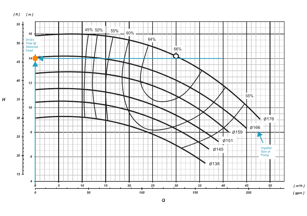
If it does not then the following should be checked:
- Motor is incorrect speed
- Impeller size is incorrect size or,
- Impeller is worn
- The ring is worn between the inlet of the pump and casing [sometimes referred to as a ‘wear ring’
- The cut water is worn
Any issues then the testing should not continue until the issues have been rectified.
Test 5: Conduct a full pump test
During the full pump test, we will measure the start and running currents of the motor and complete a full flow rate test.
Test 5a: Pump motor start and running currents
With the pump off, set the discharge valve to 50% open.
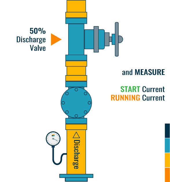
Turn the pump on measure the motor start current and ensure at full design speed/Hz.
Record the running currents of the motor.
Test 5b: Pump full flow test
From Test 5a, open the discharge valve, slowly, to 100% open, ensuring that the running amps do not exceed the full load current of the motor.
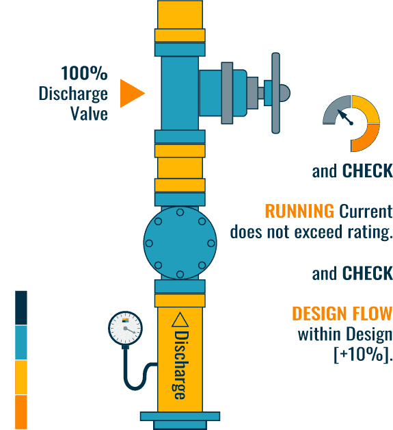
If it approaches or goes over then reduce the speed or restrict the water flow.
The objective here is to demonstrate that the pump flow rate can meet the design requirements with a tolerance of [+10%/-0%].
With the pump at full flow and the electrical current within the operational limits of the motor, complete the following measurements and document:
- Suction pressure [psi]
- Discharge pressure [psi]
- Electrical running current [amps]
- Flow rate [l/s] or [m3/s]
- Pump rotational speed [rpm]
- Pump power [KW]
From the above readings calculate the pump head pressure, as did previously, and plot the information on the pump curve with the flow rate measured.
The suction pressure measured will also provide information relating to the NPSH [Nett Positive Suction Head] requirements of the pump, which is also shown on the pump curve.
Check that the pump is operating as per the design requirements and manufacturer expectations and that the motor is sized correctly.
Control Device Functional Testing
All controls and control devices of the pumps would be functionally tested under the controls element of the Chilled Water System
Centrifugal Pump Fuctional Testing Procedure Template
To help us expand the site and create more resources, we have created the below documentation in [Microsoft Word] for download.
Click the ‘Buy Here‘ button to purchase the fully editable copy of the document below, which can be used straight away.
You will direct to our shop page.
Related Articles
FAN COIL UNIT | Week, Month, 6 months, Year & 4 Year Inspections Listed
CRAC UNIT | Functional Testing Example + Template
FACTORY ACCEPTANCE TESTING | Guideline, Agenda & Report
HOW TO WRITE | A Method Statement with download
WATER LEAK DETECTION | How it Works and Testing Method
GROUP CONTROL | CRAH & CRAC Units