The difference between a CRAC Unit System and a CRAH Unit System is how the heat is transferred and then removed/ejected from the system. A CRAC Unit transfers the heat from the system and ejects by only using the Refrigerant Cycle, whereas a CRAH Unit utilizes Chilled Water, the Refrigerant Cycle, and Condenser Water.
Below we compare and provide a high-level comparison table between the two with graphics to visually explain the fundamentals of the different systems.
To read more detail on the different types of unit see the following articles: CRAC Unit and CRAH Unit
Component Comparision Table
| COMPONENT | CRAC UNIT | CRAH UNIT |
| Unit frame | X | X |
| Panels [sides, bottom, and top] | X | X |
| Sound attenuation | X | X |
| Access doors | X | X |
| Inspection Windows | X | X |
| Base frames | X | X |
| Filters | X | X |
| Supply air plenum | X | X |
| Supply air grille | X* | X* |
| Return air plenum | X | X |
| Return air grille | X* | X* |
| Fan Section | X | X |
| Fan Motors | X | X |
| Fans | X | X |
| Fan Guards | X | X |
| Vibration isolators | X | X |
| Humidifier | X* | X* |
| Water supply and pipework [for humidifier] | X* | X* |
| Reheat coil | X* | X* |
| Dx Cooling coil | X | |
| Water Cooling coil | X | |
| Condensate drip tray | X | X |
| Condensate pipework | X | X |
| Condensate pump | X* | X* |
| Control panel | X | X |
| Control wiring | X | X |
| Temperature sensors | X | X |
| Humidity sensors | X | X |
| Network switch | X* | X* |
| Control/expansion valve | X | |
| Refrigerant pipework | X | |
| Refrigerant [R407A] | X | X** |
| Chilled water pipework | X | |
| Isolation valves | X | |
| Commissioning station/PICV | X | |
| Strainers | X | |
| Pipework temperature gauges | X | |
| Pipework pressure gauges | X | |
| Compressor | X | |
| Dx Condenser unit [external] | X | |
| Condenser fans | X | |
| Condenser coils | X | |
| Chilled water pumps | X | |
| Water-cooled chiller | X | |
| Condenser water pipework | X | |
| Condenser water pumps | X | |
| Cooling tower | X | |
| Air-cooled chiller [if no condenser water] | X*** |
*usually would be an ‘option’ | **the refrigerant noted within the CRAH Unit System is found within the chiller and what allows the heat from the chilled water system to be moved to the condenser water system before being ejected at the cooling towers | ***On some occasions the chiller used will be ‘air-cooled’ , removing the need for the condenser water equipment.
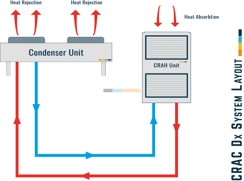
CRAC Dx System Pipework Diagram
The following diagram details a ‘typical’ system layout for a CRAC Unit Dx System.
It can be seen that the cooling process is managed and created by the condenser unit via the refrigeration process.
The condenser will be installed and located externally.

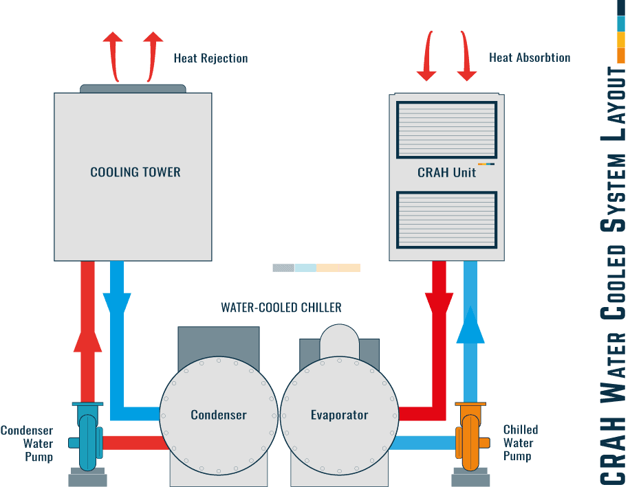
CRAH Water Cooled Chiller Pipework Diagram
The following diagram details a ‘typical’ system layout for a CRAH Water-Cooled Chiller System.
It can be seen that the cooling process is managed and created by the water-cooled chiller, which is used like a heat exchanger using the refrigeration process to transfer the heat from the chilled water system to the condenser water system, where the cooling towers will reject it to the atmosphere.
The chillers will be installed internally, and cooling towers externally.

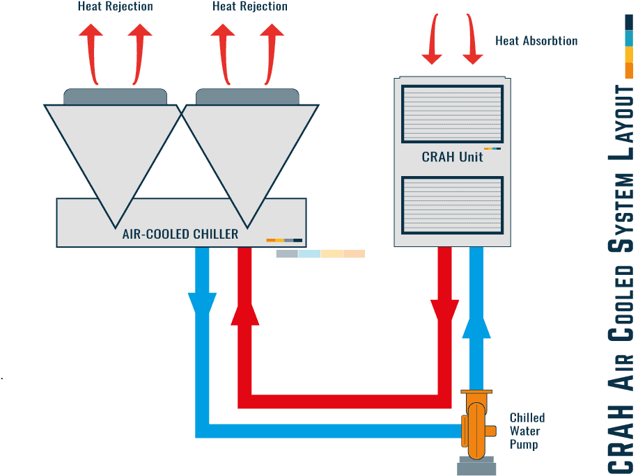
CRAH Air Cooled Chiller Pipework Diagram
The following diagram details a ‘typical’ system layout for a CRAH Air-Cooled Chiller System.
It can be seen that the cooling process is managed and created by the air-cooled chiller via the refrigeration process.
The air-cooled chiller will be installed and located externally.

⬛ Related Articles
GROUP CONTROL | CRAH & CRAC Units
CRAC UNIT | Pre-Functional CheckList
CRAC UNITS | What are they?
CRAH UNIT | Pre-Functional CheckList
CRAH UNITS | What are they?
CRAH UNIT | Functional Testing Example + Template

