Whether deploying a Hot Standby or Cold Standby strategy to condition a critical space, ‘Group Control’ will be used where multiple CRAH or CRAC Units that serve the same room need to be controlled and synchronized.
Depending on the number of units, we have found that one, two, three, or four groups could be used.
We generally find that most manufacturers/projects will use similar methods and logic.
Below we will quickly provide detail from what is Group Control to Functional Testing, to give some information on the system.
What is ‘Group Control’
Let’s take an example of a Data Hall. There will usually be multiple units installed around the perimeter of the space to help maintain its environmental condition, ‘Group Control’ will act as a ‘conductor,’ integrating and managing multiple units and their control, so each in the ‘Group’ is working in harmony.
Usually, there will be a ‘Master Unit’ for each group that,
If for whatever reason, a failure occurs on a unit, the group control will react accordingly, modifying how the remaining ones or the sensors are managed, ensuring no downtime.
Why Use it?
There are a few good reasons to use this type of system:
- Managing unit failures and the reaction of the remaining equipment,
- Managing sensor failures,
- Helping maintain a stable environment in the space with harmony across the control of setpoints,
- Allow efficient setting up of systems.
Is there a Master Unit?
Generally, there is a ‘Master Unit.’
If for whatever reason, this fails, the logic will usually instruct the next unit to become the Groups Master after a set period of time.
Who is responsible for designing and specifying the Group Logic?
The mechanical system designer will be responsible for the system’s design. Still, in our experience, this work is usually passed to the manufacturer of the CRAH units as they have a much better understanding of how their systems operate to ensure the design conditions are maintained.
How many Groups should be used?
This depends on the number of units and the space configuration; the design team, including the manufacturer, should specify this.
We have seen the following:
- 0 groups – usually in switch rooms where units are under individual control
- 1 group – upto 4 units
- 2 groups – upto 8 units
- 4 groups – upto 16 units
How to connect Groups together
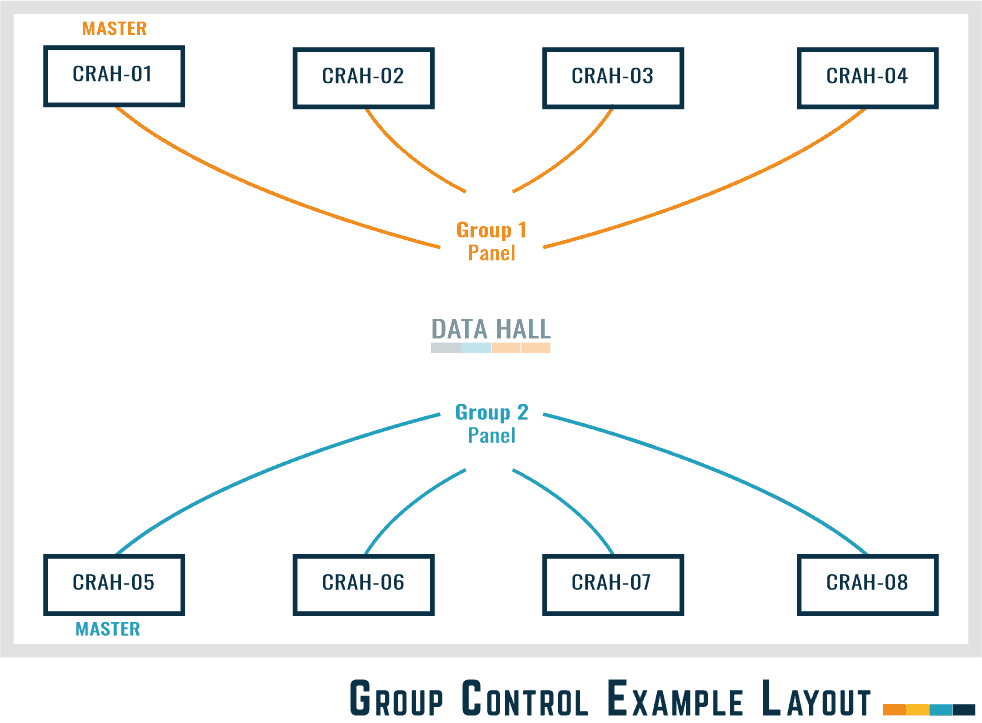
The above diagram shows how multiple units can be configured into a ‘Group.’ Groups can be wired in many different ways than the one shown. They could be opposite units, every second unit, subgroups where bigger one is split into an A/B group, etc.
Each ‘Group’ will be wired back to a network switch/panel to be controlled from and managed. Usually, UPS backed for power.
What is the common Control Logic for a COLD Standby configuration
‘COLD Standby’ means that any redundant units in the system providing resilience/backup will be in ‘Standby’ mode [Off/Cold].
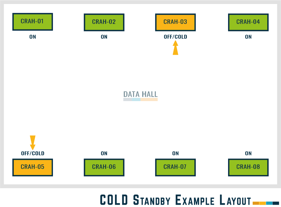
A standard control matrix for this type of layout would be:
| Ref | Scenerio | Response of Group Control |
|---|---|---|
| 1 | Failure of 1no. Running CRAH/CRAC Unit in each group. | Standby unit starts up to provide cooling, covering failed units with no impact to the environment of the space. |
| 2 | Reset and switch on the 'Failed' CRAH/CRAC Unit/s | Standby units in the group go back to 'Standby' mode. |
| 3 | Modify set point of the return air, lower than 'normal' setting | Standby units in group will start up |
| 4 | Reset return air set point back to 'normal' setting | Standby units in group will shut down |
| 5 | At the Group Network Switch, remove the power supply simulating a 'Network Failure' | All standby units in group startup, using own sensors and settings to control as out of group |
| 6 | Reconnect Network Switch so group is 'normal' | Standby units in group shutdown when required and sensors / settings reset to normal operation. |
| 7 | Fail 1No. CRAH/CRAC Unit in Group remote Supply Temperature & Humidity Sensor | CRAH/CRAC Unit with failed sensor will continue to operate using the average value of the remaining sensors in the group. |
| 8 | Reset remote Supply Temperature & Humidity Sensor | CRAH/CRAC Unit will reset using own sensor for control. |
| 9 | Fail 1No. CRAH/CRAC Unit in Group Off Coil Supply Air Sensor that controls the Cooling Valve | Affected CRAH/CRAC Unit Energy Valve Opens to 100%, standby units start if necessary based on return air temperature. |
| 10 | Reset Off Coil Supply Air Sensor that controls the Cooling Valve | Affected CRAH/CRAC Unit Energy Valve Reset to normal, standby units shut down if necessary based on return air temperature. |
What is the common Control Logic for HOT Standby configuration
‘HOT Standby’ means that all units will be running [Hot] at reduced fan speeds.
If there is a failure, the remaining units will increase fan speeds and cooling load covering the failed unit/s, providing resilience/backup.
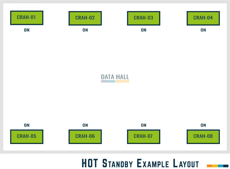
A standard control matrix for this type of layout would be:
| Ref | Scenerio | Response of Group Control |
|---|---|---|
| 1 | Failure of 1no. Running CRAH/CRAC Unit in each group. | Standby unit starts up to provide cooling, covering failed units with no impact to the environment of the space. |
| 2 | Reset and switch on the 'Failed' CRAH/CRAC Unit/s | Standby units in the group go back to 'Standby' mode. |
| 3 | Modify set point of the return air, lower than 'normal' setting | Standby units in group will start up |
| 4 | Reset return air set point back to 'normal' setting | Standby units in group will shut down |
| 5 | At the Group Network Switch, remove the power supply simulating a 'Network Failure' | All standby units in group startup, using own sensors and settings to control as out of group |
| 6 | Reconnect Network Switch so group is 'normal' | Standby units in group shutdown when required and sensors / settings reset to normal operation. |
| 7 | Fail 1No. CRAH/CRAC Unit in Group remote Supply Temperature & Humidity Sensor | CRAH/CRAC Unit with failed sensor will continue to operate using the average value of the remaining sensors in the group. |
| 8 | Reset remote Supply Temperature & Humidity Sensor | CRAH/CRAC Unit will reset using own sensor for control. |
| 9 | Fail 1No. CRAH/CRAC Unit in Group Off Coil Supply Air Sensor that controls the Cooling Valve | Affected CRAH/CRAC Unit Energy Valve Opens to 100%, standby units start if necessary based on return air temperature. |
| 10 | Reset Off Coil Supply Air Sensor that controls the Cooling Valve | Affected CRAH/CRAC Unit Energy Valve Reset to normal, standby units shut down if necessary based on return air temperature. |
Functional Testing of the Group Control
To verify and validate that the control system is operating correctly during the CRAH / CRAC Unit Functional Testing – the above schedules [scenarios/reactions] should be proved and simulated.
Or what is specific to the project.
For more information on how to functionally test a CRAH Unit, see our article - 'CRAH UNIT | Functional Testing Example + Template'
⬛ Related Articles
CRAC UNITS | What are they?
CRAC UNIT | Pre-Functional CheckList
CRAH UNIT | Pre-Functional CheckList
CRAH UNIT | Functional Testing Example + Template
CRAH UNITS | What are they?
CRAC Unit vs CRAH Unit | What’s the difference?