The dynamic flushing stage is completed to remove the majority of the debris, dirt, and particles from inside the pipework system prior to moving on to the chemical cleaning stage, which will use chemicals to move the water quality to the next stage.
The cleaner the system is for that stage, the fewer chemicals will be needed, reducing time and costs.
Also, removing debris from the system will assist to prevent blockages in terminal unit coils, sensitive equipment such as balancing and control valves, and the possibility of water quality degradation.
This step is critical because it will set the tone for the entire process and determine whether it will take longer or shorter to finish all of the tasks.
We have included at the end of this article a full example PDF of a flushing and cleaning method statement
Below we will go through the steps and stages required to successfully complete this element of the flushing and chemical cleaning procedure, before moving to the next stages.
Steps to Flush & Clean a System:
The following steps will usually be conducted when completing the flushing and cleaning process on a mild steel pipework system:
- [1] Ensure the system can be flushed properly via document reviews [drawings/specificaitons].
- [2] Agree on the flushing and cleaning strategy, methods, and any water conservation that will be used.
- [3] Discuss and agree on the witnessing and inspection requirements.
- [4] Discuss and agree on the sampling requirements.
- [5] Write and approve documentation to allow works to commence.
- [6] Complete all pre-requisite checks.
- [7] Review and inspect any temporary setup, water, drainage, and chemical dosing.
- [8] Inspection of tools and instruments to be used.
- [9] Conduct a dynamic flush.
- [10] Chemical clean.
- [11] Clean flush.
- [12] Neutralization of pipework surfaces.
- [13] Passivation of pipework surfaces.
- [14] Inhibit system.
- [15] Biocide dosing.
- [16] Backflushing equipment and terminal units.
- [17] Ongoing chemical treatment of installation.
- [18] System Maintenance till handover.

[1] Ensure the system can be flushed properly via document reviews
Design Reviews |
The initial place to start the review process is at the design stage. Refer to our article ‘FLUSHING & CLEANING | Pipework Systems Overview’ for additional information on the design considerations that should be implemented during the design phase of the project, to ensure the flushing and cleaning works are able to be completed successfully, they can be summarized as follows:
| Ref | Check |
| 1 | Will the new installation be integrated into an existing system, or will it be a new independent standalone system? |
| 2 | How will the system be pressurized to ensure no air can enter? |
| 3 | What are the expected handover requirements/processes to the building owner/operator? |
| 4 | What guidelines should be used and referenced to ensure the works are completed in line with an industry-standard? |
| 5 | What method of cleaning is to be used – 100% to drain or use side stream filters, sand filters etc to conserve water?. |
| 6 | Will there be a requirement for any licenses to discharge the flushing water to drain? |
| 7 | Is there an existing water treatment company working within the building for the client that should be specified to complete the chemical works? |
| 8 | Once the flushing has been completed, what will the time period roughly be until handover? |
| 9 | Will the system need to be maintained by the project after completing flushing, if so what will need to be completed? |
| 10 | What are the expectations with the chemicals being used? |
| 11 | Is there any pipework in the system larger than 300mm, if is what will the method be for cleaning? |
| 12 | Is the system allowed to be flushed via the permanent system pumps, if are then what is the requirement after flushing has been completed?. Do the pumps need to be inspected and serviced? |
| 13 | If the system pumps are not allowed to be used and temporary pumps are required, who is responsible to supply and install them?. |
| 14 | The size of pumps that are required, are they available on the market for rental? |
| 15 | Will there be enough space in the project to install the temporary pumps? |
| 16 | How will the temporary pumps be powered, temporary supplies, or permanent?. |
| 17 | Will there be enough power available if using temporary electrical supplies for the pumps? |
| 18 | What is the requirement with regards to the provision of flushing loops?. |
| 19 | What is the requirement with regards to the maximum dead leg allowed?. |
| 20 | Will there be mains water available for filling, venting, and flushing activities? |
| 21 | What is the expected minimum mains water supply size needed? |
| 22 | Will the drainage be ready and connected to the mains at the time of flushing? |
| 23 | What is the expected minimum drainage size needed? |
| 24 | What is the final system quality testing requirement? |
| 25 | What is the final system documentation requirement? |
Commissioning Reviews |
The commissioning consultant [CxA] should conduct their own review of the project documentation using the design specifications, layout drawings, and schematics, to understand if all requirements have been allowed.
For a list of items to check, use the above table for the designer.
Any observations/comments should be discussed and actions agreed upon with the project team with modifications and amendments being made where required.

[2] Agree on the flushing and cleaning strategy
Once the general/main contractor has been instructed on the project, and after they have had time to get their feet under the table, workshops and discussions should be organized to develop a flushing strategy for the project.
The strategy could take several weeks to agree and have approved by the project team, and why need to start the process early.
Some items that would be discussed and agreed are:
- Method of flushing and cleaning [including any large pipework].
- Sampling requirements, onsite and of site testing of water quality.
- Flow rate measurement method.
- Pass/fail criteria.
- Total system flush or sectional flushing.
- Expected timeline and programme/sequence including power, water, and drainage availability.
- Permit to works/licenses to be obtained.
- Control of the works to ensure there is no interruption, including water, drainage, and power
- Equipment sourcing, delivery period, and its placement/installation into the system including powering up.
- Flushing loop installation [temporary or permanent].
- Management of water and system after completion of the works until handover to the building operator
Water-saving and its efficient use
The standard method of flushing and cleaning, which is described later, can use and discharge a huge amount of water from the filling and draining required throughout the total process.
This is not environmentally friendly and also in some cases can re quire special licenses from a government body or water supplies company, to allow discharge of the chemicals and quantity of water needed.
So to combat this a temporary sidestream filtration system can be used installing cartridges or bags, that will filter a percentage of the water being flowed around the system, collecting the debris and particles, reducing the need for constant draining and filling of water.
Additional information on this can be found at the end of this article.

[3] Agree on the witnessing & inspection requirements
As we know, the flushing and cleaning can be a bit of a freight train, once it is started it does not stop for anything, all hands to the pumps and something that really should take 12 weeks the Project Manager is trying to force through in 3 weeks.
With that in mind, the witnessing and inspection requirements need to be agreed upon and understood from the earliest stages.
The earliest point for understanding would be for the commissioning manager to include the requirements within the commissioning specification/guidelines.
Purpose of inspecting and witnessing
Flushing and cleaning, if not completed properly or successfully resulting in less than ideal results is one of the biggest problems a project can have.
As long as the system is being cleaned it can’t move to the next stages.
Shortcutting stages and steps will generally result in problems, especially in the future once it has been running for some time resulting in a challenge of understanding what the actual issue is and then how to fix it, usually the system can’t be switched off and flushed again as one, so maybe needed to complete in sections.
Expensive works and all due to people shortcutting.
So, the general purpose is to ensure that the works have been completed in line with the agreed method and that it is fully documented and if there are any issues later on, the documentation, witnessing and inspecting, should provide enough evidence that everything was completed in line with expectations.
Facilities teams have also been known to try and blame the construction project when systems have issues because they are not maintained properly.
It is your Insurance…
What should be inspected and witnessed?
The following should be at the top of the list when it comes to the inspecting and witness of the works:
- Calibration certificates.
- Incoming mains water quality.
- Temporary System Set-Up, water, and drainage connections.
- Pre-requisites.
- Installation of flushing loops.
- Periodic checks on general flushing works.
- Flushing velocities.
- Cleaning of strainers and filters.
- Collecting of samples and analysis onsite.
- Analysis of samples provided to a laboratory.
- Final documentation that will provide evidence that the system was cleaned properly.
- Monitoring of system from completion of flushing till handover to owner.
[4] Agree on the sampling requirements
Sampling the closed-circuit chilled water and heating system during and after the flushing works provides an insight into the condition of the system and the quality of the water being circulated.
For the system there will generally be 4 different reasons to test and analyze the systems:
| When | Flushing/Chemical Specialist | Commissioning Manager [CxA] | Building Facilities / Operator |
| [a] Between system filling and flushing works starting | Responsible | Oversee | |
| [b] During the cleaning and flushing process | Responsible | Oversee | |
| [c] After completion and before handover | Responsible | Oversee | |
| [d] After the handover | Responsible |
[a] Sampling prior to flushing the system
Prior to the system being flushed, it will be filled to allow pressure testing to take place.
There is usually a period of time between the filing, pressure testing and flushing activities, sometimes depending upon the size of the system it can be months.
Once pressure tested, leaving the clean mains water in the pipework for a period of time will start to corrode the pipework, cause issues with bacteria and degrade the water, this will result in a longer flush and clean.
To reduce the risk of this and any programme impacts, the flushing/chemical specialist should be employed to manage the quality of the system from the minute water is introduced.
They can then provide advice, sampling, and rectification if there are any issues.
Regarding the sampling quantities and where they should be taken, and when, the following table can be used from the British Standard:
| Size of System | Quantity of Samples | Where to Sample | Time between Samples |
| <3,000 Liters and <2 Terminal Units | One | Main Plant Area | every 4 weeks |
| <3,000 Liters and <25 Terminal Units | Two | Main Plant Area + Remote Location on the System | every 4 weeks |
| >=3,000 Liters or >=25 Terminal Units | Two + agreement with flushing/chemical specialist | Main Plant Area + Remote Location and any additional inline with the agreement with flushing/chemical specialist. | every 4 weeks |
[b] Sampling during the flushing process
Sampling during the construction phase will be carried out to ensure that the system water quality is meeting certain criteria prior to moving on to future steps.
The stages when the sampling will take place will be discussed and agreed upon with the commissioning manager/flushing and chemical cleaning specialist, prior to being detailed within the method statement.
There will be two types of tests performed, depending on the step/stage:
- Site sampling and testing
- Laboratory testing
The points at which to sample are detailed below in the method and procedure section.
[c] Sampling after the flushing process is completed
After the completion of the cleaning and before handover there is usually a period of time where the system and commissioning tasks have moved on to water/hydrostatic balancing and equipment startup and functional testing.
During this time the water and pipework system needs to be maintained, chemically treated, and sampled.
As noted in the above table, this will be the responsibility of the flushing and chemical specialist and overseen by the commissioning manager, to ensure all documentation and records are kept and maintained.
The sampling will be conducted in line with the British Standard BS 8552 [Sampling and Monitoring of Water from Building Services Closed Systems. Code of Practice].
They can then provide advice, sampling, and rectification if there are any issues.
Regarding the sampling quantities and where they should be taken, and when, the following table can be used from the British Standard:
| Size of System | Quantity of Samples | Where to Sample | Time between Samples |
| <3,000 Liters and <2 Terminal Units | One | One in Main Plant Area | every 2 weeks |
| <3,000 Liters and <25 Terminal Units | Three | One in Main Plant Area + Two in Remote Locations on the System | every 2 weeks |
| <8,000 Liters or 25 to 80 Terminal Units | Four | One in Main Plant Area + Three Remote Locations on the System | every 2 weeks |
| <20,000 Liters or 80 to 250 Terminal Units | Five | One in Main Plant Area + Four Remote Locations on the System | every 2 weeks |
| <40,000 Liters or 250 to 500 Terminal Units | Six | One in Main Plant Area + Five Remote Locations on the System | every 2 weeks |
| >40,000 Liters or >500 Terminal Units | Various | One in Main Plant Area + [no. of terminal units/500]x5* | every 2 weeks |
*if a system has 1000 terminal units the number of samples will be 11 [one in the plant area and 10 in remote locations]
[d] Sampling after the works completed
Once the project and system has been handed over, the facilities company will take responsibility for managing and sampling the water quality to ensure it continues to be within the system parameters and requirements.
The sampling would generally be taken inline with the above table ‘sampling after the process is completed’ but at different frequencies:
| Size of System | Quantity of Samples |
| Source Water | One-off Sample |
| Closed Pipework System | Generally Quarterly |
The facilities team will also have the system monitoring equipment operational and will use that to provide information between their own samples being taken and analyzed such as:
- Corrosion Coupons [see our article ‘CORROSION COUPONS | and Coupon Racks’]
- Corrosion electronic monitoring equipment
The analysis will cover monitoring the following types of quality metrics:
- Suspended Solids
- Conductivity
- pH
- Total Alkalinity
- Total Hardness
- Nitrates
- Sulfates
- Chlorides
- Total Iron
- Dissolved Iron
- Total Copper
- Molybdate
- Phosphates
- Glycol
- Total Viable Count [TVC]
- Pseudomonas

[5] Write and approve documentation to allow works to commence.
The general/main contractor via their sub-contractors should write and issue the works method statement and testing script for the strategy that has been agreed upon.
The document should be written in a step-by-step format, with enough detail to allow the project and onsite teams a full understanding of how the works are to be conducted.
Within each step, there should be an area to take notes and sign/approve by the team prior to the next steps commencing. This will allow for the whole process to be documented and stored for any future reference.
The CxA/commissioning consultant’s role will be to review, comment and approve the document.

[6] Complete all pre-requisite checks
All pre-requisite checks should be completed to ensure that the installation is ready for the flushing activities to commence, based upon an approved document that will usually form a section within the method statement.
The inspection and approval process will usually follow:
- General/main contractor ensures that all pre-requisites have been completed [self-check]
- The General/main contractor will then invite the client, designer, and CxA to inspect and witness the requirements that have been met.
- Client, designer, and CxA will inspect and approve for the next steps to commence.
We have written a seperate article on the below, to read more go to FLUSHING & CLEANING | Pre-Works Checklist

[7] Review and inspect any temporary setup, water, drainage, and chemical dosing
Part of the pre-requisites above will be to set up the system to allow the flushing to be completed successfully.
There will, within the method statement be a section that details any temporary equipment, instruments, and pipework that is needed and would usually cover:
- [a] Mains water connection and availability.
- [b] The system is filled and vented.
- [c] Drainage connection and availability.
- [d] Chemical connection and chemical availability.
- [e] Temporary pumps.
- [f] Pipework connections for pumps.
- [g] Power supplies.
- [h] Flushing loops and bypasses.
- [I] Dead Legs.
- [j] Regulation valves/flow reading devices.
- [k] Strainers.
- [l] Water tanks.
- [m] Discharge tanks.
These should be checked during the pre-requisite inspections, below is some information that should be considered relating to some of the requirements.
We have created an article on the temporary setup for closed-loop flushing covering, in more detail, some of them below. ‘***’
[a] Temporary mains water supply connection
A mains water supply will be needed to ensure there is an availability of clean water for system filling and flushing activities.
It will usually be installed in the header at the suction side of the pumps so the water is pulled in from the mains.
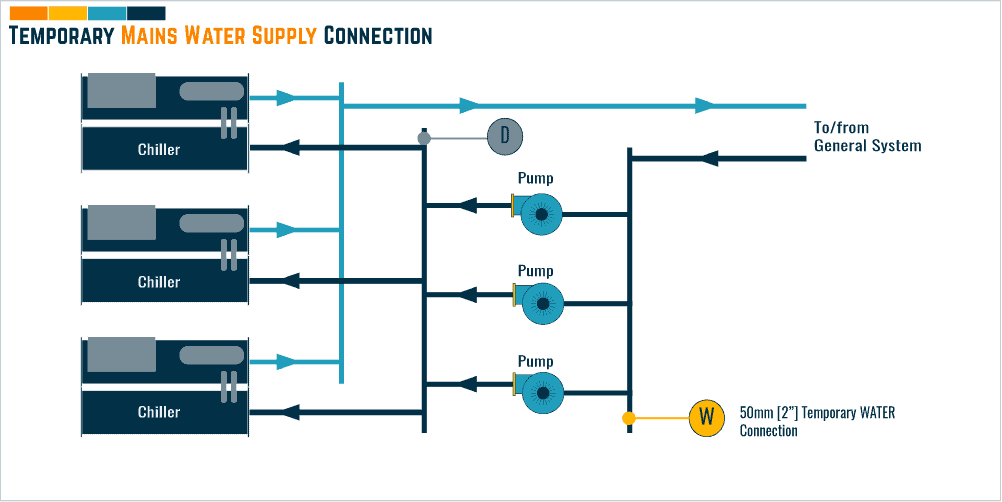
The water supply should be dedicated, avoid using the temporary water feed that is used for the general site water. It needs to be fully managed and controlled by the contractor that has been employed to complete the water flushing.
If a dedicated supply can not be provided then a temporary water tank should be installed to provide a buffer whilst flushing in case of any issues with the water supply.
Depending upon the size of the system being flushed, the cold water main should be sized as follows:
| System Size [ltrs] | Mains Pipework Size [mm] | System Size [gallons] | Mains Pipework Size [Inches] | Location Installed |
| <2000 | 25 | <530 | 1.0 | The suction side of pumps, usually in the header |
| 2,000 to 10,000 | 40 | 530 to 2,650 | 1.5 | The suction side of pumps, usually in the header |
| >10,000 | 50 | >2,650 | 2.0 | The suction side of pumps, usually in the header |
Testing the Mains Water Quality
Prior to using the mains water, it should be tested for quality against the project specification. This is to ensure that the water that is being used to fill the system is of the same / better quality than what the specification requires the pipework system to be.
The water should be sampled and tested at least 14 days prior to the pressure testing commencing, as this will be when the system is filled with the raw water.
Mains water quality requirements
The requirements of the mains water will usually be specified by the design consultant and be measured in a few locations:
- At the mains coming into the building
- At the point where it is connected to the closed system to feed water – this is to understand if there are any issues between the mains incomer and the connection.
If you want an idea of what would be expected we have seen the following requirements when sampling and testing a mains water system prior to pressure testing and flushing:
| Type | Requirement |
| pH Value | 6.0 to 8.5 |
| Turbidity | <0.2 to 1.5 ppm |
| Water Hardness | 10 to 40 CaCo |
| Total viable count (TVC) | <10000 cfu/ml |
| Pseudomonads | <1000 cfu/ml at 30 degrees C |
| Sulfate (mg/l SO4) | <250 mg/l |
| Chloride (mg/l Cl) | <250 mg/l |
| Total Dissolved Solids (TDS) | 25 to 150 ppm |
Where the water quality does not meet the project requirements, it may need to be pre-treated before introducing it to the system.
The chemical cleaning specialist should provide advice on this.
[b] Filling & Venting the Pipework System
After the above testing has been completed and is successful, the water can be used to fill the system whilst also venting to remove and release any buildup of air.
If it is expected that the water will be sat in the system for some time, this will usually be the case for most large commercial and industrial projects, it should be dosed with biocide and inhibitors to slow the formation of biofilms and corrosion.
Obviously, if chemicals are introduced, all operatives should be made aware of this with the relevant risk assessments completed.
[c] Temporary drainage water connection
The drainage water connection size should be of the same size and diameter as the mains water connection, usually, be a reinforced flexible pipe, and installed on the discharge side of the pumps.
![[068] Drainage Connection for Flushing and Cleaning Pipework](https://constructandcommission.com/wp-content/uploads/2021/11/068-Drainage-Connection-for-Flushing-and-Cleaning-Pipework.png)
This is to allow, during the flushing, it to provide the same drainage flow rate as the incoming water for the system to be balanced.
| System Size [ltrs] | Drainage Pipework Size [mm] | System Size [gallons] | Drainage Pipework Size [Inches] | Location Installed |
| <2000 | 25 | <530 | 1.0 | The discharge side of pumps, usually in the header |
| 2,000 to 10,000 | 40 | 530 to 2,650 | 1.5 | The discharge side of pumps, usually in the header |
| >10,000 | 50 | >2,650 | 2.0 | The discharge side of pumps, usually in the header |
One of the biggest issues can be, on greenfield development, is that the building’s drainage may not be connected to the utility mains drainage in time for the activities to take place, so better to check early on the programming of this.
If it is not, then alternative measures will be needed, such as temporary tanks etc.
[d] Chemical connection and availability
Depending upon the stage of flushing and cleaning, there will usually be a requirement to introduce a chemical to aid the process and will be specified by the specialist chemical engineer on the project, it should be checked that these are available, some common ones are listed below:
- Acid Cleaner and formulated cleaning products – To aid the removal of surface oxides from the internal surface of the pipework.
- Biocide/Biodispersants – To reduce bacterial levels in the system water and help remove biofilms [depending on requirements of the system]
- Passivators and Inhibitors – To manage the rate of corrosion within the system.
To introduce the chemicals to the system, there will need to be somewhere to inject it, either via a dosing pot or chemical treatment tanks.
[e] Temporary Pumps
Generally, it is accepted that the permanent system pumps are used for flushing to help the process and make things easier, they are generally sized correctly and will be onsite connected to the pipework so no real need to cut in temporary supplies etc.
If they are used, it is good practice to, at the end of flushing and before the hydrostatic balancing takes place, that the manufacturer is instructed to inspect the pumps, externally and internally, to ensure there is no damage and to change any parts, prior to confirming the warranty is still in place.
Where the use of the permanent pumps is not allowed and there is no option but to bring in temporary ones, they should be installed and ready for the flushing activities to take place.
![[068] Temporary Pump for Flushing and Cleaning Pipework](https://constructandcommission.com/wp-content/uploads/2021/11/068-Temporary-Pump-for-Flushing-and-Cleaning-Pipework-1.png)
Note the delivery times of them early in the project as sometimes, unless they are sat in someone’s cupboard, they can be on a few months lead time.
If using any type of pumps [perminant or temporary], they will need to be pre-functional tested and part functional tested prior to operating and set to their correct flow rates.
If want to understand more about this, see our article ‘Pump Commissioning and Alignment’ for how they should be set up and commissioned.
[f] Pipework connections for temporary pumps
Make sure all pipework connections are installed, correct size, and ready.
[g] Power supplies
To ensure the pumps can run, there will need to be an electrical supply, either temporary or permanent.
Consideration should also be given to any electrical testing of the power supplies, switchboards, motor control panels, cables that will be needed to safely run the systems.
[h] Flushing loops and bypasses
To allow the water to circulate around the system, but not cause issues with the sensitive equipment and coils that are installed, flushing loops and bypasses should be installed to allow the water to bypass them and recirculate back to the pumps, allowing a complete circuit.
There are usually 2 types of bypasses used:
- Permanent Bypass – this is the best option as will be installed with the system pipework and be left in place after works have compelted. It does not need additional work to replace, like with a temporary loop, and will allow the facilities teams the ability to use in the future if ever needed. Note the bypass will need to be managed during the terminal unit/equipment maintenance works, at least each month blow it thourhg to remove the risk of any contaminated water.
- Temporary Bypass – this is probably the most common, and is installed as a temporary measure, to be removed once the flushing has been completed. We wonder if it saves time or money, but contractors seem to love it, probably not ever analysed the data on using them.
![[068] Flushing and Cleaning Pipework Bypass Configuration](https://constructandcommission.com/wp-content/uploads/2021/11/068-Flushing-and-Cleaning-Pipework-Bypass-Configuration-1.png)
Ensure all bypasses are set up properly and equipment is isolated [this should be the case from pressure testing as should not run dirty system water into the units just yet].
See our article on flushing bypasses for types and layouts that can be used ‘***’
[i] Dead legs in pipework
A dead leg is a section of pipework where water can’t be circulated or flowed and becomes stagnant allowing the buildup of bacteria and corrosion on the internal surfaces of the pipework.
Generally, they should be avoided and design solutions put in place to ensure that they do not exist, reducing the risk for future contamination of the system.
![[068] Pipework Dead Leg](https://constructandcommission.com/wp-content/uploads/2021/11/068-Pipework-Dead-Leg-1.png)
Where they can’t be avoided, good practice can be put in place to ensure minimal risk and impact to the system. The steps that should be taken are:
- They should be no longer than 3 pipe diameters
- They should be looped to allow cleaning and future water flow
- Up to and including 50mm [2 inches] the loop should be full pipework size [full bore]
- Over 50mm the loop should be 50% of the pipework size.
[j] Regulation valves/flow reading devices
As noted below under ‘dynamic flushing’, to ensure the majority of debris is removed from within the system, prior to the chemical treatment taking place the water should be circulated and pre-determined flow rates.
This will ensure debris and particles up to 5mm are carried away to drain.
See more on this below.
[k] Strainers
Strainers are used in the process to protect the pumps from debris flowing through them causing damage to the impeller and internals.
The strainers should be inspected to ensure that the mesh is clean, and not damaged.
![[068] Strainer Positions for Flushing and Cleaning Pipework](https://constructandcommission.com/wp-content/uploads/2021/11/068-Strainer-Positions-for-Flushing-and-Cleaning-Pipework.png)
On some occurrences, it is better to use a temporary mesh or have a replacement ready for handover, as the clients will usually ask for them to be replaced.
[l] Water tanks
If there is a risk that the mains water supply could be interrupted or even not be available, affecting the progress of the activities, then a temporary water tank can be used to provide storage of water, creating a buffer.
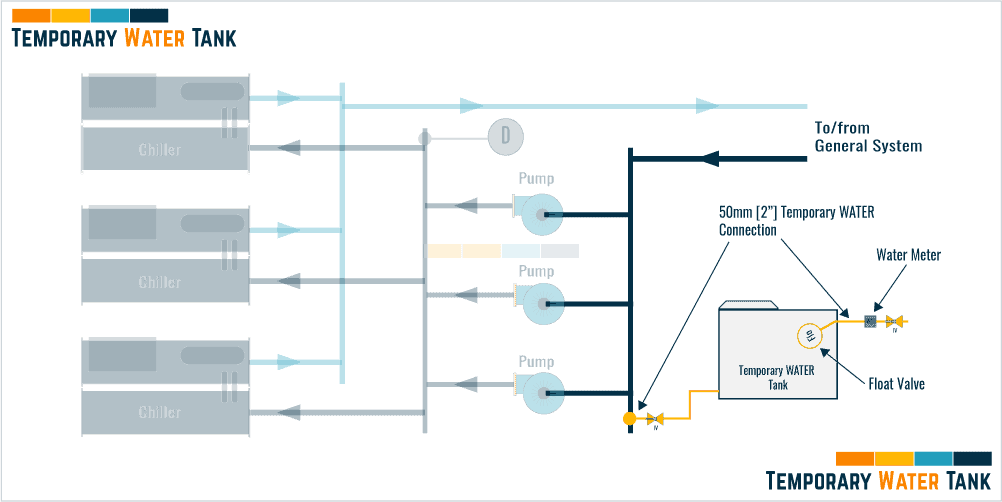
Like with the pumps, this should be thought about early on in the project as there is a possibility would be on a long lead time if can’t get one off of the shelf.
[m] Discharge tanks
In some scenarios, as noted with the temporary drainage pipework above, if there is no mains connected then there will be a requirement to tank and truck away from the site the discharged water.
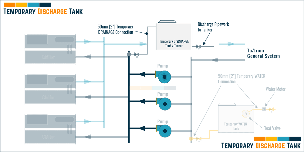
Tanks will be needed for this task and should be thought about early on in the project as there is a possibility with the size of tanks potentially needed, there would be on a long lead time if can’t get one off of the shelf.
[8] Inspection of tools and instruments to be used
To ensure that the works are successful and all data obtained correct, there will be a requirement for tools and instruments to be available.
Some tools will need to have an up-to-date calibration certificate and this should be provided prior to the testing and works taking place.
Below is a list that can be used as a base, of what would be expected to be used:
| Ref | Type of Instrument |
| 1 | Water manometer |
| 2 | Ultrasonic flowmeter |
| 3 | Onsite water sampling test kit |
| 4 | Electrical multimeter |
| 5 | Clamp meter |
Ok, now time to move on to the actual flushing works…
[9] Conduct the Dynamic Flush
Currently, there is no requirement to complete a static flush, if are utilizing BSRIA BG 29 as a guideline. The activities start at the dynamic flushing stage, so once all the documentation, pre-requisites, and system setup is out the way. The dynamic flushing can commence.
…After we have detailed the importance of flushing velocities…
Pipe Flushing Velocity
During the dynamic flushing stage, water will be circulated at a specific flow rate within the horizontal pipework, depending upon its internal diameter [mm], to dislodge and move the built-up debris and material.
As noted in the guidelines, the typical size of debris found within a new mild steel system would be around 5mm in diameter and the flushing velocities have been developed to ensure debris up to and including this size can be moved around the system until it is removed via the filters, strainers or drain connection.
The required flow rates can be calculated by taking the design flow rate of the section of pipework and adding [10%], or from general tables as noted below:
Velocity Requirements vs. Pipe Size
If using the tables, the guidelines cover pipework sizes from 15mm [1/2 inch] to 300mm [12 inches]. Once the sizes go above 300mm, as noted above, there will be a requirement to take the design flow rate and add [10%].
If the system pipework sizes are well in excess of 300mm [12 inches], and the size makes it impractical to use the traditional method of flushing and cleaning, other strategies should be implemented such as:
- Conduct off-site prefabrication to allow the cleanliness of the pipework to be managed and inspected, this would need to be a strategy from the outset of the project with a strict QA/QC process.
- Physically clean the internal surfaces of the pipework using manual methods. This can easily be done, just time-consuming and very labor-intensive as sections of pipework will probably need to be removed and reinstalled.
- Understand from the chemical specialist if there is a way of using dispersants to suspend particles and lower velocities.
Measuring Velocities around the System
To ensure the correct velocities are being experienced by the system during the works and the project requirements are being met, readings and measurements will need to be taken at strategic locations.
There are usually 2 types of measurement that can be completed to understand the velocity, with both usually deployed on a project for their specific task.

Ultra Sonic Measurements
A portable ultrasonic flowmeter is mounted on bare pipework and can measure the velocity of the fluid flowing by using sound waves.
It does not need any valves so can be used to verify in areas where there are no permanent measuring devices.
According to documentation, if used and mounted correctly, in line with the manufacturer’s requirements, the Ultra Sonic device that is used for measuring flow rates within a pipework system will have an accuracy of approximately +/-5%.
They can be very handy to have onsite.
If there are any concerns relating to the accuracy of them, even if there is a calibration certificate, we would usually do a test and cross-reference against a permanently installed commissioning station/regulation valve.
System Regulation Valve Measurements
Within the design of the pipework system, there will be measuring devices such as double regulating valves and commissioning stations that can be utilized to gain a reading for the flow rates around the system.
Dynamic flushing steps
The below steps are based upon a primary-only, closed pipework system, assuming no side stream filtration is being used.
Primary closed pipework system
A standard strategy would be to flush and clean the larger-sized pipework first [usually the plant room area] prior to moving to the smaller pipework.
This is to ensure that the smaller pipework is not hit with a huge amount of dirty water and all the debris passed through it.
Once the larger pipework has been dynamically flushed, the smaller pipework will be cleaned, with most of the water being quite clean, there should be few issues.
The below PDF can be used as a reference when reading the steps below.
Step 1 – Ensure the system is set up in line with the drawing [large pipework]
![[068] Flushing and Cleaning Main Pipework](https://constructandcommission.com/wp-content/uploads/2021/11/068-Flushing-and-Cleaning-Main-Pipework.png)
Step 2 – Turn pumps on and run
Make sure they are not running over their stipulated current ratings and, the flow rates are correct to meet the flushing requirements.
They should have already been partially commissioned in the previous steps so there should not be any issues, but better to be safe than sorry.
Step 3 – Once pumps are running and circulating water, gradually open the mains cold water feed
This will allow fresh water to flow into the system, replacing the water being discharged as per the next step.
Step 4 – With the mains cold water open, slowly open the drainage/discharge valve
Balance the discharge water with the mains water feed
[feed water = discharge water] = good
If the system is not balanced and is discharging more than feeding there could be issues with pressurization, then air coming into the system causing issues with the overall process.
Step 5 – Allow the water to circulate around the system
Ensure strainers are regularly checked, this will usually be the one at the suction side of the pumps, by taking pressure readings across them.
If they are found to be blocked with debris, shut the system down, clean and reinstall them, if unable to do it live.
Step 6 – Measure the water velocities to ensure in line with the dynamic flushing requirements
This would usually be done by the orifice plates or regulation valves near the pumps.
Ensure the relevant parties witness the readings and sign any documentation.
Step 7 – Keep the pumps running until the water at the drain runs clear
The objective of this step is to get the drain water clear.
Step 8 – Once the water is clear, stop the pumps and close the makeup water & discharge valves
Remove and clean the strainer baskets.
Step 9 – Repeat steps 1 to 8 for any other pipework circuits that are to be dynamically flushed
This is to clean the sections of pipework that have not yet been cleaned.
Step 10 – Run all pumps through all circuits for a final flush of pipework
Should not be expected much to happen here but run for a few minutes until the drain runs clear again.
Step 11- Conduct a dissolved iron test
Taking samples as per the sampling section, measuring the dissolved iron levels in the water, BSRIA notes that they should not exceed 3mg/l, unless otherwise noted by the chemical specialist.
Step 11 – Ensure all documentation is fully completed, witnessed, and signed
This is important as will ensure that the activities are able to be proved later if any issues.
Step 12 – Ensure the system is set up in line with the drawing [smaller pipework]
![[068] Flushing and Cleaning Branch Pipework](https://constructandcommission.com/wp-content/uploads/2021/11/068-Flushing-and-Cleaning-Branch-Pipework.png)
Step 13 – Turn pumps on and run
Make sure they are not running over their stipulated current ratings and, the flow rates are correct to meet the flushing requirements.

Pretty decent value, to take the electrical readings and data from the equipment that is required for documenting.
Step 14 – Once pumps are running and circulating water, gradually open the mains cold water feed
This will allow fresh water to flow into the system, replacing the water being discharged as per the next step.
Step 15 – With the mains cold water open, slowly open the drainage/discharge valve
Balance the discharge water with the mains water feed.
[feed water = discharge water] = good
If the system is not balanced and is discharging more than feeding there could be issues with pressurization, then air coming into the system causing issues with the overall process.
Step 16 – Allow the water to circulate around the system
Ensure strainers are regularly checked, this will usually be the one at the suction side of the pumps, by taking pressure readings across them.
If they are found to be blocked with debris, shut the system down, clean and reinstall them, if unable to do it live.
Step 17 – Measure the water velocities to ensure in line with the dynamic flushing requirements
This would usually be done by the orifice plates or regulation valves near the pumps.
Ensure the relevant parties witness the readings and sign any documentation.
Step 18 – Keep the pumps running until the water at the drain runs clear
The objective of this step is to get the drain water clear.
Step 19 – Once the water is clear, stop the pumps and close the makeup water & discharge valves
Remove and clean the strainer baskets and, clean all dirt pockets.
Step 20- Conduct a dissolved iron test
Taking samples as per the sampling section, measuring the dissolved iron levels in the water, BSRIA notes that they should not exceed 3mg/l, unless otherwise noted by the chemical specialist.
Step 21 – Ensure all documentation is fully completed, witnessed, and signed
This is important as will ensure that the activities are able to be proved later if any issues.
[10] Chemical cleaning process
For our article on the next step detailing the chemical cleaning see our article ‘CHEMICAL CLEANING FLUSHING | Procedures & Sequence’

SIDE STREAM FILTER | Its use in Flushing
Side-Stream Flushing will follow the same steps as Dynamic Flushing.
The difference will be, instead of only cleaning the water by replacement [fill and drain], a temporary sidestream filtration system, using cartridges or bag filters, can be installed in the return pipework, that will filter a percentage of the water being flowed around the system, collecting the debris and particles, reducing the need for constant draining and filling of water.
Filters will need to be changed/cleaned through the process, and different grades may be required during the cleaning depending on the stage.
Below is a layout showing how the filter could be piped temporarily for the flushing to be completed:
![[068] Temporary Side Stream Filter for Flushing and Cleaning Pipework](https://constructandcommission.com/wp-content/uploads/2021/11/068-Temporary-Side-Stream-Filter-for-Flushing-and-Cleaning-Pipework.png)
Pipework Flushing & Cleaning Functional Procedure Template [PDF]
⬛ Related Articles
FLUSHING & CLEANING | Pre-Works Check List
CORROSION COUPONS | and Coupon Rack
FLUSHING & CLEANING | Pipework Systems Overview
FLUSHING & CLEANING | Monitoring after Flushing
BACK FLUSHING | Procedure & Sequence
CHEMICAL CLEANING FLUSHING | Procedure & Sequence