Data Center redundancy is a critical component of the overall facility design, duplicating key equipment and infrastructure, such as power supplies, cooling systems, and network connections, to ensure that maximum ‘Uptime/Availability’ is provided and ensuring that the systems remain operational in the event of a failure, minimizing any downtime and service interruptions.
In this article, we explore the redundancy including the different types that can be found and used in data centers and their importance, discussing the implementation process and best practices for ensuring the systems are always operational and how they relate to the ‘Uptime’ Tier Standards.
🟩 Importance of Redundancy
As noted above in the introduction, redundancy is essential for ensuring high availability and minimizing the risk of downtime or service interruption to a critical facility. In today’s digital age, where businesses rely on technology to operate, even a few minutes of downtime can cause major disruption or be extremely costly.
- Improved reliability: The reliability of a data center will be increased by providing backup/redundant systems and equipment/components in the event of failure,
- Increased availability: Data center operators can ensure that critical services and applications are always available to users, providing better Uptime and increased availability,
- Reduced downtime/impacts: Minimizes the impact of downtime and reduce the time it takes to restore services in the event of an outage or failure,
- Improved fault tolerance: Helps the data center withstand faults and/or errors in individual components, without affecting the overall operation of the system,
- Increased flexibility: With redundant components, data center operators can carryout maintenance and/or upgrades on one set of equipment or system without affecting the overall operation of the critical space,
- Higher scalability: Redundancy makes it easier to scale, meeting any increased demand, by adding more plant and equipment if the general infrastructure allows,
- Enhanced disaster recovery: Redundancy can help a data center recover from disasters such as fires, floods, or earthquakes by providing backup systems and data storage.
- Improved performance: Redundancy can help with overall performance of the data center operations and balance the load on the systems,
- Single point of failures: Redundancy can help reduce risk of single points of failure within the systems installed,
- Improved customer satisfaction: Redundancy can help ensure that critical services are always available, leading to improved customer satisfaction and loyalty.
- Better clients: Designing and installing certified/redundant systems will allow better marketing opportunities, if selling space for co-location, resulting in a better grade of clients.
🟩 What does ‘N’ or ‘N+X’ Mean?
In the context of data center infrastructure, redundancy is often described using the notation ‘N+X’, where ‘N’ represents the number of primary components needed to support the normal operations/design requirements, and ‘X’ represents the number of additional backups or redundant components.
Systems, equipment, components and instruments that are usually covered will be the ‘critical’ ones, needed to maintain the temperatures, humidity, power supplies and data connections to the data hall.
🟩 Types of Redundancy Explained
There are several types of redundancy that are commonly used in data centers, with the top 5 being – N, N+1, N+2, 2N and 2N+1.
Below we provide a high-level overview of each.
🟧 ‘N’ Explained
As noted above, the letter ‘N’ is used to represent the total quantity of equipment and components relating to the critical systems that are needing to be active to support a data centers everyday operations.
‘N’ can refer to any type of equipment component that is necessary for the data center to function properly, such as power supplies, cooling systems, or networking devices.
🟨 Applicable Tier Standard
An ‘N’ configured system would generally equal a Tier 1 Data Center – Basic Capacity, if also accompanied with single distribution paths for the power and cooling.
Tier 1 is the lowest tier rating, providing the most basic capacity level with no redundancy provided by the designed and installed cooling or electrical equipment, and major disruptions experienced if any system/component failures or if maintenance is to be completed.
🔗 To read more about the Uptime Tiers see our article: DATA CENTER TIERS | Uptime - 1, 2, 3 & 4 Explained
🟨 Example of ‘N’
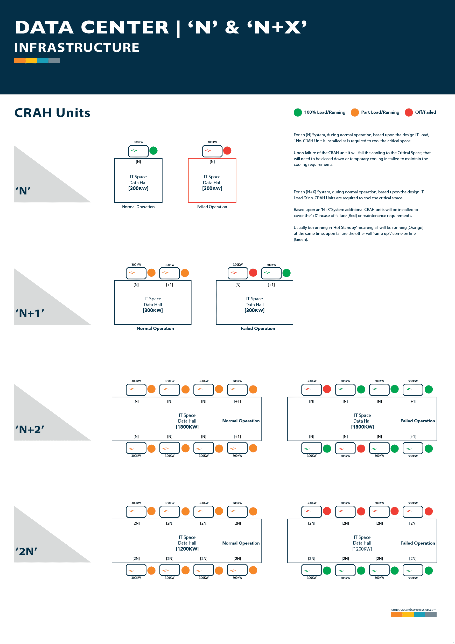
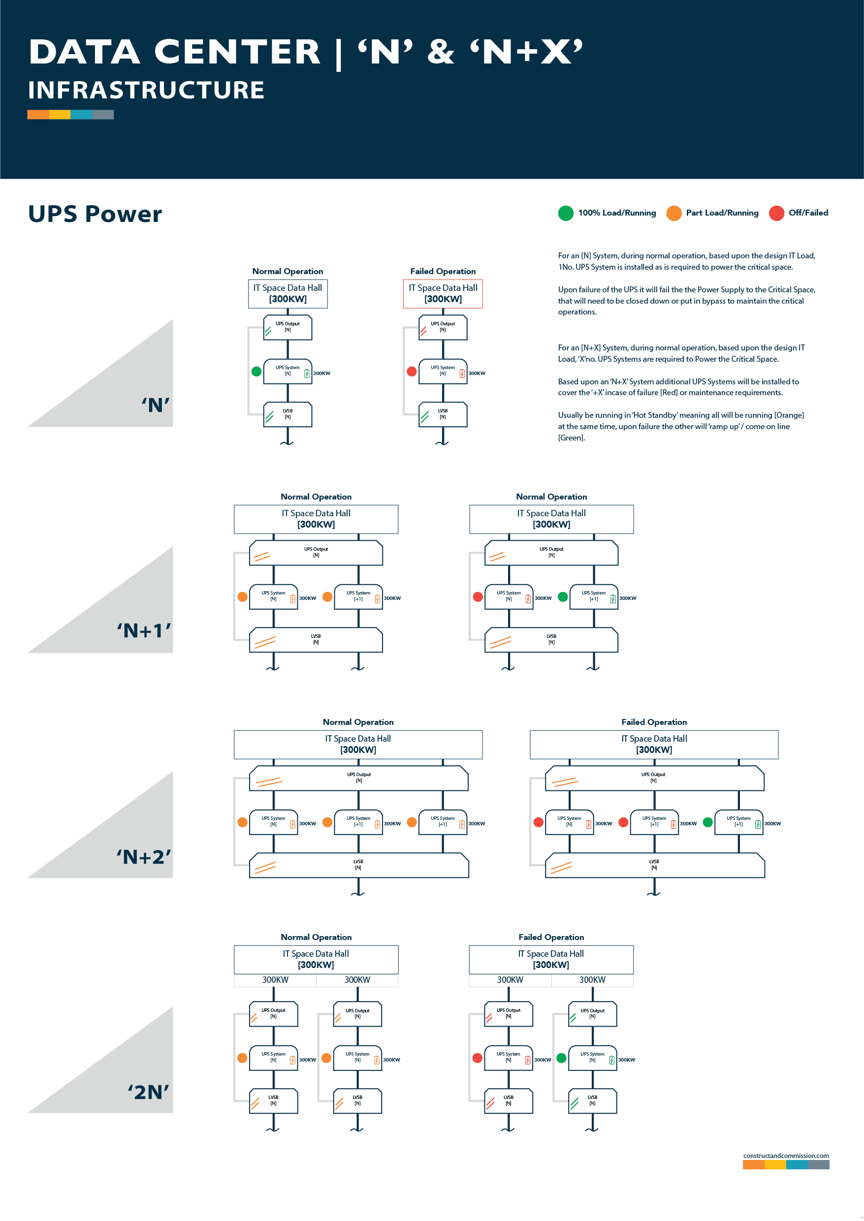
We have detailed a simple system graphic at the end of this section – ‘N+X’ Graphic Samples – that shows an ‘N’ configuration for a CRAH unit and UPS system.
Within the system graphic, we have included only the CRAH/UPS equipment for example, but there are other items of plant and equipment that could also be included in an [N] design and have been included below for reference:
Cooling Equipment
- [N] Cooling Tower,
- [N] Water Cooled Chiller,
- [N] Pumps,
Electrical Equipment:
- [N] Generator,
- [N] High Voltage Switch Board,
- [N] Transformer,
- [N] Low Voltage Switchboard,
- [N] Power Distribution Unit,
If any part of the system fails then the data hall operation will probably be interrupted, meaning down time.
We have been asked several times to create a complete document package covering everything we have uploaded to the site.
So it's taken some time, but here it is....126No. Documents for you to download in Microsoft Word, Microsoft Excel & PDF Formats.
CLICK THE BUY HERE TO SEE/DOWNLOAD A FULL LIST OF DOCUMENTS INCLUDED...
🟧 ‘N+1’ Explained
‘N+1’ refers to a level of redundancy in which a facilities system builds on the previous ‘N’ by adding additional critical components to support it if another similar one is failed, goes off line or put into maintenance.
🟨 Applicable Tier Standard
An ‘N+1’ configured system would generally equal a Tier 2 Data Center – Redundant Site Infrastructure Basic Capacity, if also accompanied with single distribution paths for the power and cooling or with multiple distribution paths be a Tier 3 – Concurrently Maintainable.
Tier 2 & 3 designs build on the Tier 1 design, providing additional redundant critical power and cooling capacity/components to the systems which will allow the facility to have a higher margin of safety and ‘uptime/availability’.
🟨 Example of ‘N+1’
If it is calculated that a data hall has an expected IT Heat Load of 300kW, with the [N] requirement to provide cooling being 1No. 300kW CRAH Unit, two units will be installed, so incase the [N] fails the [+1]/2nd will take over the load with no interruptions to the operations.
This would be similar with the electrical components, if the design requires a UPS, two will be installed of the similar sizes.
We have detailed a simple system graphic at the end of this section – ‘N+X’ Graphic Samples – that shows an ‘N+1’ configuration for a CRAH unit and UPS system.
Within the system graphic, we have included only the CRAH/UPS equipment for example, but there are other items of plant and equipment that could also be included in an [N+1] design and have been included below for reference:
Cooling Equipment
- [N]+1 Cooling Tower,
- [N]+1 Water Cooled Chiller,
- [N]+1 Set of Pumps,
Electrical Equipment:
- [N]+1 Generator,
- [N]+1 High Voltage Switch Board,
- [N]+1 Transformer,
- [N]+1 Low Voltage Switchboard,
- [N]+1 Power Distribution Unit,
If any component fails or needs maintenance then the impact to Data Hall operations will be limited.
🟧 ‘N+2’ Explained
Usually, used in larger systems or where CRAH/CRAC’s are installed across two corridors, see graphic below, ‘N+2’ refers to a level of redundancy in which a facilities system builds on the previous ‘N+1’ by adding another layer of components to support the operations incase of failure or maintenance requirements.
🟨 Applicable Tier Standard
An ‘N+2’ configured system would generally equal a Tier 2 Data Center – Redundant Site Infrastructure, if also accompanied with single distribution paths for the power and cooling or if including various distribution paths, a Tier 3 – Concurrently Maintainable.
As noted under the ‘N+1’ System, Tiers 2 & 3 build on the Tier 1 design, providing additional redundant critical power and cooling capacity/components to the systems which will allow the facility to have a higher margin of safety and ‘uptime/availability’.
🟨 Example of ‘N+2’
If it is calculated that a data hall has an expected IT Heat Load of 1,800kW, with the [N] requirement to provide cooling being 6No. 300kW CRAH Units, eight units will be installed, so incase upto [N+N] fails the [+2]/7th and 8th units will be available take over the load with no interruptions to the operations.
This would be similar with the electrical components, if the design requires a 1No. UPS, three will be installed of the similar sizes.
We have detailed a simple system graphic at the end of this section – ‘N+X’ Graphic Samples – that shows an ‘N+2’ configuration for a CRAH unit and UPS system.
Within the system graphic, we have included only the CRAH/UPS equipment for example, but there are other items of plant and equipment that could also be included in an [N+2] design and have been included below for reference:
Cooling Equipment
- [N]+2 Cooling Tower,
- [N]+2 Water Cooled Chiller,
- [N]+2 Set of Pumps,
Electrical Equipment:
- [N]+2 Generator,
- [N]+2 Transformer,
- [N]+2 Low Voltage Switchboard,
- [N]+2 Power Distribution Unit,
If any component fails or needs maintenance then the impact to Data Hall operations will be limited.
🟧 ‘2N’ Explained
Being not very common due to the costs and installation requirements, a [2N] system provides the most protection to the data center facility, ensuring a fully isolated redundant backup for all critical infrastructure components.
In a typical [2N] system, there are two independent sets of power and cooling equipment/components and infrastructure – mirroring each other, with each set capable of supporting the entire critical load of a Critical Space or Facility incase a failure of anyone.
🟨 Applicable Tier Standard
A [2N] configured system would generally equal a Tier 4 Data Center – Fault Tolerant, if also accompanied with multiple distribution paths for the power and cooling systems.
🟨 Example of ‘2N’
If it is calculated that a data hall has an expected IT Heat Load of 1,200kW, with the [2N] requirement to provide cooling being 4No. 300kW CRAH Units, 2No. sets of four units [eight in total] including all cooling plant and equipment will be installed, so incase up to [N] fails the [other N System] units and equipment will be available to take over the load with no interruptions to the operations.
This would be similar with the electrical components.
We have detailed a simple system graphic at the end of this section – ‘N+X’ Graphic Samples – that shows an [2N] configuration for a CRAH unit and UPS system.
Within the system graphic, we have included only the CRAH/UPS equipment for example, but there are other items of plant and equipment that could also be included in an [2N] design and have been included below for reference:
Cooling Equipment
- [2N] Cooling Tower,
- [2N] Water Cooled Chiller,
- [2N] Set of Pumps,
Electrical Equipment:
- [2N] Generator,
- [2N] Transformer,
- [2N] Low Voltage Switchboard,
- [2N] Power Distribution Unit,
If any component fails or needs maintenance then the impact to Data Hall operations will be limited.
🟨 ‘N+X’ Graphic Samples
Below we have included some graphics that give examples of the ‘N+X’ configurations and can be downloaded for FREE from our shop by clicking the button:
⚠️ These are only provided as examples, there are many other configurations that can be used, depending upon the design and client requirements.
⬜ CRAH Unit Example
⬜ UPS System Example
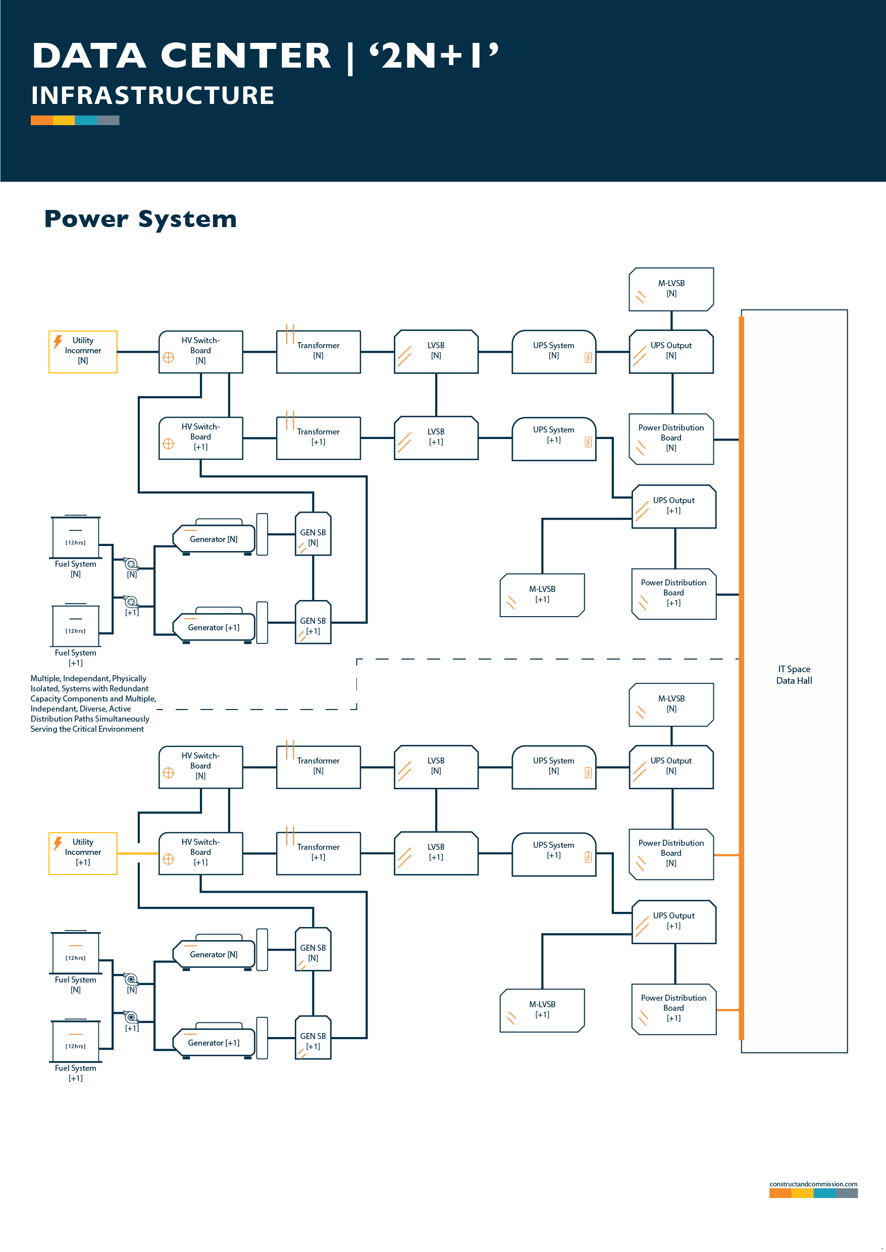
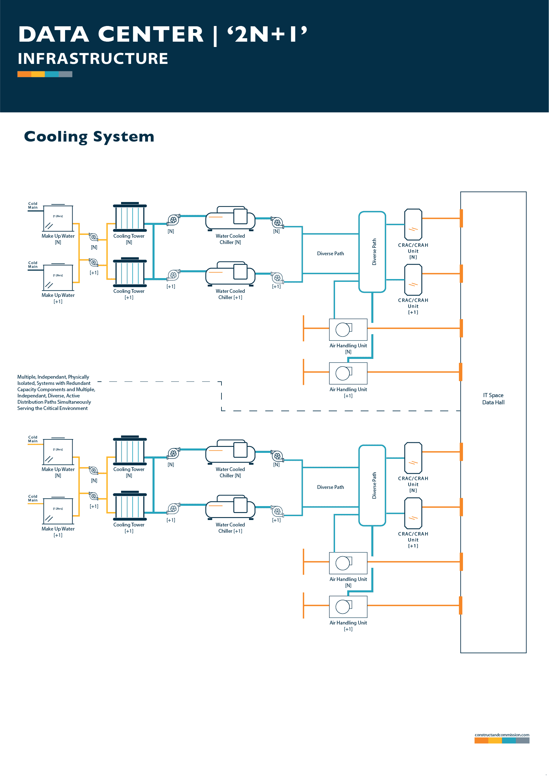
🟧 ‘2N+1’ Explained
[2N+1] systems are designed as a [2N], as described above having two independent systems for power and cooling, but with the addition of some redundant critical components for each as in an [N+1] design… [2N+1].
This is the ultimate in redundancy, but like the [2N] system its quite rare to see as extremely expensive to deploy.
🟨 Applicable Tier Standard
Like with a [2N] system, a [2N+1] configured system would generally equal a Tier 4 Data Center – Fault Tolerant, if also accompanied with multiple distribution paths for the power and cooling systems.
🟨 Example of ‘2N+1’
If it is calculated that a data hall has an expected IT Heat Load of 1,200kW, with the [2N+1] requirement to provide cooling being 4No. 300kW CRAH Units, 2No. sets of four units [eight] will be installed with an additional 1no. per system [2], so total of 10 units.
This would be similar with the electrical components.
We have detailed a system graphic below, that shows an [2N+1] configuration for a typical data center, it can.
If any component fails or needs maintenance then the impact to Data Hall operations will be limited.
We have written an article on how to obtain the Uptime Tier Ratings, see: UPTIME TIER RATINGS | The Simple Steps to Obtain them
🟨 ‘2N+1’ Graphic
⬜ Power Systems [2N+1]
⬜ Cooling System [2N+1]
⬜ References/Citations
- EIA. (2021). Data Center Energy Use in the United States.
- Hewlett Packard Enterprise. (2021). Data center power and cooling white paper.
- Network World. (2022). Survey: Outages, staffing challenge data centers.
⬛ Related Articles
LEVEL 0 – DATA CENTER Cx | Design & Planning
LEVEL 1 – DATA CENTER Cx | Factory Witness Testing
DATA CENTER | 0, 1, 2, 3, 4, 5, 6 Levels of Commissioning
LEVEL 2 – DATA CENTER Cx | Delivery, Installation & Pre-Start Up
DATA CENTER COMMISSIONING | What is it?
DATA CENTER | Commissioning Guideline & Template