Providing a quick and fast response to water leaks in some applications could be the difference between your business operating or having to be taken offline and services interrupted.
This can be achieved with a Water Leak Detection System. The following will describe how they work and how they should be tested to ensure continual operation.
What is a Water Leak Detection System?
A water leak detection system is a system that monitors its environment for any water leaks or spills via probes or sensing cables that could go unnoticed. They would generally activate an alarm to alert the engineering team of an issue and to allow them to respond quickly and efficiently.
Water Leak Detection Systems are commonly found in critical areas of Data Centres, Data Halls, Server Rooms, Plant Rooms, Offices, Pantries, Hospitals, and Commercial Applications.
Water Leak Detection Equipment
Within a water leak detection system the following equipment will usually be seen:
Leak Detection Panel
The Leak Detection Panel is the system’s brain and can be supplied as a physical button push or touch screen. All cabling from the field is connected, including any interfaces with the Building BMS system to provide data back to the control room and operation engineers.
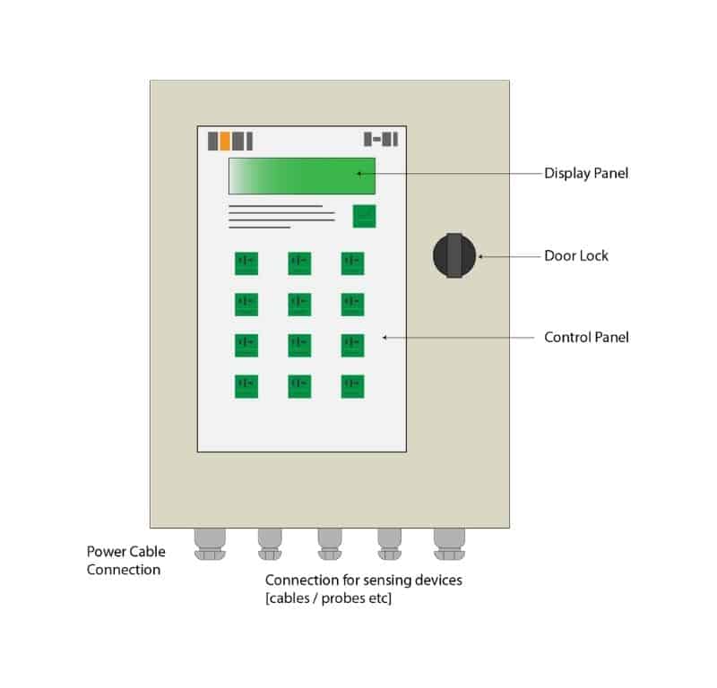
The Leak Detection Panels role is to continuously monitor the system and, once detected an issue, to trigger an alarm [audable & usually send to BMS] to detail the type of problem (Water Leak / Moisture detection or Cable Break). Data will be captured, including the date, time, zone, location for records.
Some panels will incorporate integrated maps of the water leak detection installation to highlight the fault on the touch screen display.
If there is no option of integrated maps included, then there should be a paper copy available at each panel for reference.
Consideration should be given as to the type of power supply the system is connected to. General power or emergency/generator backed power.
Ancillaries
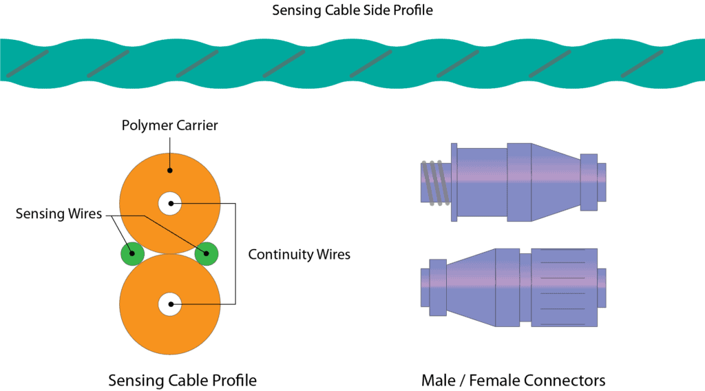
Sensing Cable/Rope
Water Leak Detection sensing cable is designed to detect and pinpoint where leaks or moisture has been noted within the system and is used to cover large areas of the floor, wrap-around pipework, or be installed into long runs of drip trays. Usually, it will be supplied in fixed lengths and is flexible.
Depending upon the manufacturer, the cable can be made up of multiple cores, usually covering 2 for Leak Detection, 2 to provide Power, 2 for communication, and 2 to determine if there is a cable break.
Connectors are installed at the ends of the cables to allow joining multiple ones together to provide longer length and coverage and these connectors will usually have some sort of visual status that will also show if an alarm has occurred on the cable.
Spot / Probe Type Sensor
Spot / Probe type sensors are generally used for smaller areas or for spot leak detection such as areas under plant and equipment / bunded areas. They are designed to find and locate leaks or moisture in focused locations.
The base of a spot detector is manufactured with 2 probes, and when water/moisture touches both probes at the same time, completing a circuit and triggering an alarm.
Clips / Tags
Clips are used to ensure the cable is fitted, so it is held in position touching the surface it is protecting.
Tags are usually installed to note the cable number/zone and distance from the panel. They should be installed every 2m around the system.
What different types of Water Leak Detection Systems are there?
Usually there are 4 types of systems found:
- Single Zoned System
- Single Zoned Distance Read System
- Multi-Zoned System
- Multi-Zoned Distance Read System
Single Zoned System
A Single Zoned Water Leak Detection System will monitor an area via sensor cable, spot/probe/pad type, or a combination of all; and if moisture is detected then will alarm for the Zoned area. The operators will need to investigate the zone to locate the leak/spill.
Single Zoned Distance Read System
A Single Zoned Distance Read Water Leak Detection System will monitor an area via sensor cable, spot/probe/pad type, or a combination of all; and if moisture is detected then will alarm for the Zoned area + distance locate on the system [usually within 1m]. This results in a quicker response from the operators as they will understand where the leak/spill is detected.
Multi Zoned System
A Multi-Zoned Water Leak Detection System traditionally will monitor multiple zones via sensor cable, spot/probe/pad type, or a combination of all connected to separate connections and at the control panel at the same time. If moisture is detected then an alarm will be sent for the Zoned area. The operators will need to investigate the zone to locate the leak/spill.
Other types of Multi Zoned Systems are on the market that allows multiple Zones to be monitored from sensors connected in series, so one sensor cable connected in a string can run through multiple zones.
Multi Zoned Distance Read System
A Multi-Zoned Distance Read Water Leak Detection System traditionally will monitor multiple zones via sensor cable, spot/probe/pad type, or a combination of all as per the above Multi-Zoned Water Leak Detection System. If moisture is detected then will alarm for the Zoned area + distance locate on the system [usually within 500mm]. This results in a quicker response from the operators as they will understand where the leak/spill is detected.
Other types of Multi Zoned Systems are on the market, which allow multiple Zones to be monitored from sensors connected in series, so one sensor cable connected in a string can run through multiple zones.
Water Leak Detection Installation Examples
- Under Raised Floors – as would be hard to see if a leak occurs
- Laid on Slabs/Floors – where there is a risk of leakage but the area is not patrolled often
- Wrapped around Pipework – usually on the outside of the insulation in risers or at high/low level
- Drip Trays – where it would be difficult to see any issues from the ground
How to Test a Water Leak Detection System
Within most construction projects, there will be a requirement for the testing and commissioning of the newly installed or modified water leak detection system.
Below provides some guidance on what would generally be expected:
Who is Responsible
General/Main Contractor
The General/Main Contractor will liaise and coordinate with the Client Team [where employed] for all testing and commissioning activities.
Vendor/Sub Contractor
The Vendor/Sub Contractor who has installed the system will be responsible for the testing, commissioning, and validating the installation operates inline with the client/specification requirements.
They should conduct a self-test before inviting the General/Main Contractor for witness.
Client Team
If a client team has been employed to validate systems and installations, they shall be in attendance during all witnessing.
Equipment & Instruments
The following equipment and instruments should be available for the testing:
- Digital Multi Meter
- Clamp Meter
General Pre-Requisites:
The general pre-requisites will include a list of all items that will need to be completed before allowing the testing to commence. These would cover:
- Delivery inspection sheets
- Installation inspection sheets
- Documentation requirements
- Testing pre-checks of installations etc
- All Installation to be complete with no objection status
- Latest approved shop drawings included and marked up with test area etc.
- Self-Testing completed, and test certificates included with a pass result.
- Permit to work systems reviewed and, where required; training completed understanding any risks and shutdowns that may be required.
- Water leak detection fed from the UPS supply.
- Areas to be cleaned and free from dirt/dust.
- Drawings to be available at each WLD panel showing clearly the zones/meterage/markings for each cable on the system
- BMS to be available and operating to prove all alarms including Graphics
- All cables to be accessible
- Ensure that all panels are free of alarms and BMS is clear
Testing Tolerances
For the majority of testing, there will be a requirement to adhere to and be within certain parameters/tolerances.
These will usually be detailed in the project specifications, codes, guides, standards, and regulations.
| Leak Detection Tape/Rope | Leak within +/-1m of the alarm description |
| Alarm at BMS | Within 10 seconds |
Method of Testing
- Check voltage/current at each panel
- With water, make a cloth damp and dab onto the cable at the point of the first test point [as directed]
- After the cable has been wetted, check the alarm panel corresponding to the cable to ensure an alarm (visual and audible) has been registered and a distance has been provided with zone, at the panel, that corresponds to where the leak was tested on the drawings, this should also be registered at the BMS system
- If the point does not alarm at the local panel or BMS then a failure should be given and the testing should move on to the next point, after 3 points of failure the testing should be abandoned and investigations carried out, moving to the next system
- Once alarm confirmed, clear leak and check BMS to ensure the alarm is not still active
- Mark all results, including meterage on the drawing and test sheet following this section
- Once the system has been proved a cable break test should be conducted in the following way
- Review the drawings and installation to determine 5no. areas where cables are connected, mark these on the drawings – making note of the distances as well
- Once complete, start at the first cable and test by pulling the cable apart at the connectors
- After the cable has been ‘broken’, check the alarm panel corresponding to the cable to ensure an alarm has been registered and a distance has been provided, at the panel, that corresponds to where the cable was broken on the drawings, this should also be registered at the BMS system
- Once alarm confirmed, clear issue and check BMS to ensure the alarm is not still active
- If a solenoid valve is fitted then this should activate upon detection
- Mark all results, including meterage on the drawing and test sheet following this section
Testing Sheet/Certificate
The testing sheet should include the following as a minimum.
Main Test Part
- Panel ID Number
- Volt Reading
- Amp Reading
Cable checking and other items
- Reference number
- Cable Number
- Area / Zone served
- Meterage of where the leak is on drawing
- Meterage of leak on panel
- Cable Break
- BMS Alarm
- Solenoid Operation [ If installed; usually on plumbing system]
- A signature field for witnessing
⬛ Related Articles
AIR-COOLED CHILLER | Pre-Functional Checklist Template + Download
NFPA 79 & OSHA Emergency Stop Requirements with Checklist
COMMISSIONING CHECKLISTS | The 3 Types Explained and Templates Listed
CRAH UNIT | Functional Testing Example + Template
COOLING TOWERS | All 38 components explained
COOLING TOWER | Preventative Maintenance Inspections