An air handling unit consists of multiple components, with its main function being the primary piece of equipment within a ventilation system, to take recirculated or unconditioned fresh air from the outside, treat and condition it with coils, humidifiers, and controls before blowing it through ductwork to the spaces required.
The units are standard and can be found in most commercial or residential applications.
🟩 What are the different types of AHUs available?
Generally, there are two common types of AHU that we come across, with it all being about the fan position:
- Draw through unit [most common]
- Blow through unit
🔗We have written an article covering what should be checked and inspected throughout the installation, pre-commisisoning and commisisoning stages for an Air Handling: 'AIR HANDLING UNIT | Pre-Commissioning Inspection Checklists'
🟧 DRAW through unit
For a ‘draw through’ unit, the fan’s position is AFTER the cooling and heating coils allowing the air to be ‘pulled’ through them, as seen in the diagram below:
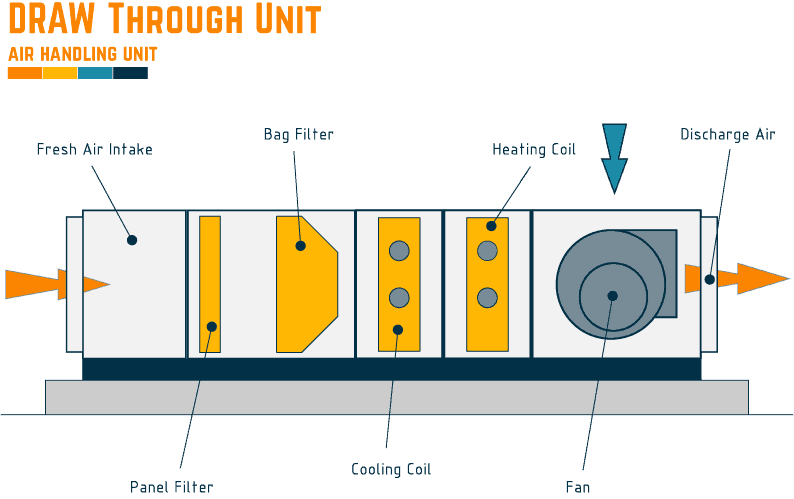
🟨 Advantages:
There are several advantages:
- The distance between the fan and the coil is smaller due to a stable airflow across the coil,
- Less risk of condensation blow over [due to lower air velocities],
- The coil can manage the heat rejection from the fan motor as installed prior.
🟨 Disadvantages:
The main disadvantage of this configuration is that the heat generated by the fan motor will create a higher air temperature after the coils, this will mean, within the design, before the air passes over and through the fan, it will need to be a lower temperature to allow the heat to be absorbed and not affect the required design condition.
🟧 BLOW through unit
The fan’s position is located BEFORE the cooling and heating coils for a ‘blow-through’ unit, blowing air through them, as seen in the diagram below:
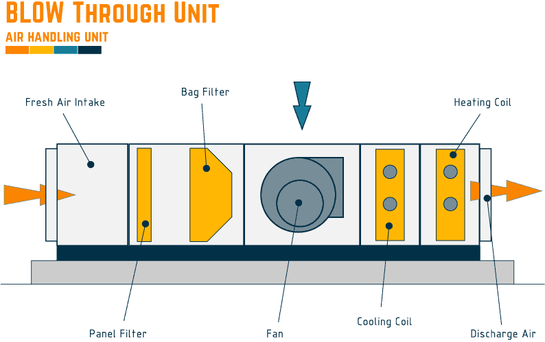
🟨 Advantages:
The main advantage of this configuration is that the heat generated by the fan motor will be managed and conditioned by the overall performance of the cooling coil, meaning that the leaving temperature is lower.
🟨 Disadvantages:
There are several disadvantages:
- The distance between the fan and the coil is larger due to managing the turbulent air from the fan hitting the coil, ensuring it is stable. It can be managed by installing a perforated diffuser plate, but that adds resistance to the system,
- Additional consideration should be given to the overall coil face velocities,
- Risk of condensation blow over [due to increased air velocities],
- The coil entering temperature at the cooling coil will be slightly higher due to the fan motor heat output.
🟩 Where are they installed and located?
Units are usually found within the following types of buildings:
- Industrial,
- Commercial,
- Hotel and Entertainment,
- Hospital,
- Data Centers,
- Larger houses.
Within these buildings, they can be found installed in the following locations:
- Externally on roofs,
- Internally within large plant rooms
- Internally within smaller air handling unit rooms [AHU Rooms]
🔗We have written an article covering what should be checked and inspected throughout the operational stage [Preventative Maintenance] for the Air Handling Unit, see our article: 'AHU | Preventative Maintenance Checklist covering Weekly to 3 Years + Download'
🟩 What components do they consist of?
An AHU will generally consist of the following components:
- Cased/Metal box
- Frame
- Air Intake
- Intake Damper [modulating]
- Frost Coil [water/dx/electric]
- Pressure differential sensors [various]
- Temperature sensors [various]
- Mixing Box
- Return duct
- Mixing Damper [modulating]
- Panel Air Filter
- Blower fan
- Bag Air Filter
- Thermal Wheel
- Cooling Coil [water/dx]
- Condensate Tray
- Heating Coil [water/dx/electric]
- External condenser [if using dx]
- Modulating/on/off valve [heating and cooling]
- Humidifier
- Discharge
- Discharge Damper [modulating]
- Controls
- Smoke Detector
- Emergency Stop
🟧 Case/Metal box
Usually made of galvanized steel, the case will form the unit’s outer skin to contain the unit’s components and allow the air to move in the direction required.
🟧 Frame
The frame is used for a couple of reasons; it allows the casing to be assembled around it and provides spaces for the components to be installed, such as cooling and heating coils.
🟧 Air Intake
The air intake is an opening near where the fan will be installed, allowing fresh air to be sucked/brought from the outside, where it will then be treated and conditioned before exiting the unit at the ‘discharge’, treating the spaces the system is serving.
🟧 Intake Damper [modulating]
A modulating intake damper combines a volume control damper [VCD] with a motor to ‘modulate’.
It is usually installed at the air intake to control the total fresh air flow entering the unit based on the overall equipment control logic/sequence of operation.
🟧 Panel Air Filter
There are usually two sets of filters installed within the unit, primary and secondary types, with the ‘panel filter’ being the primary.
The panel filter will be located before any of the internal unit components and after any mixing boxes. It acts as the first line of defense, filtering out larger debris or dust from the incoming air and protecting the more expensive ‘bag filter.’
🟧 Bag Air Filter
The bag filter, the secondary filter, is usually installed after the panel filter. It has much more refined filtering capabilities and is used primarily to catch tiny dust particles, pollen, and contaminants, helping indoor air quality.
🟧 Differential Pressure Sensors
Differential pressure sensors [DPS] are usually installed on either side of the filters, fans, or coils to monitor them, reporting back to the BMS and giving an early warning for any blockages or issues with airflow.
🟧 Frost Coil [water/dx/electric]
A frost coil can be seen and used for a couple of reasons, mainly for colder climates where there is a risk of the external air entering the air handling unit and freezing the primary/secondary filters and water coils used for conditioning the air.
It can also be used to help lift the temperature of the incoming air before letting it flow through other components, based on the design requirements.
🟧 Temperature Sensors
Temperature sensors are used to monitor and report the overall air temperatures within the unit at different locations to help the control process and conditioning of the air in line with the control logic/sequence of operation.
They are generally positioned before and after coils/humidifiers.
🟧 Mixing Box
Mixing boxes or air-mixing plenums are positioned close to where the fresh/external air is brought into the unit allowing the return air from a conditioned ceiling void or space to be managed and mixed with the fresh air pulled in from outside, helping with maintaining the overall system efficiency.
Any return air not mixed will then be expelled and exhausted externally.
🟧 Return duct
Used in conjunction with the mixing box above, a return air duct is used to manage the conditioned air back to the air handling unit, where it can be mixed with the fresh air.
🟧 Mixing Damper [modulating]
To aid the operation of the mixing box, a motorized damper is required to allow the correct quantities of air to mix.
The damper will consist of a volume control damper [VCD] combined with a motor to allow it to ‘modulate.’
🟧 Blower fan
The primary way to manage air into and through an air handling unit is by using a ‘blower fan’.
Depending upon the unit’s overall configuration, multiple fans can be installed, using an impeller to move the air and being driven by ‘belts’ or ‘directly’.
🟧 Thermal Wheel
Designed as a ‘Heat Recovery Wheel’/’Air Plate Heat Exchanger’, this is a large wheel manufactured like a ‘coil’ and designed so that each of its revolutions allows it to pass through the return and fresh air paths, picking up the temperature, warm air in the winter or cooler air in the summer from the system return and discharging it into the fresh air to help with the overall system efficiency, without the need for mixing.
🟧 Cooling Coil [water/dx]
A water or direct expansion [refrigerant] cooling coil is installed to help cool the fresh or mixed air passing through the unit.
As the air passes through the coil, it will be cooled by either chilled water or refrigerant that will absorb the heat and then take it away to be discharged at the chiller or external condenser.
🟧 Condensate Tray
If a cooling coil is installed, there will usually be a condensate tray. The tray is installed under the coil to catch any condensation expected to form during the cooling process.
It will be manufactured from galvanized or stainless steel, connected to a water trap and pipework to allow the captured water to flow out of the unit and be discharged to a drain.
🟧 Heating Coil [water/dx/electric]
A water or direct expansion [refrigerant] heating coil is installed to help warm the fresh or mixed air passing through the unit.
As the air passes through the coil, it will be warmed by either hot water or refrigerant that will provide additional heat, absorbing the cooler temperature and then take it away to be discharged at the chiller or external condenser.
🟧 External condenser [if using dx]
If the unit is using a refrigerant to cool or heat the coils, there will be the need for an external condenser.
The condenser will be positioned at the end of the refrigerant pipework and manages the discharging of the excess cold or hot temperatures that have been removed by the refrigeration cycle.
🟧 Modulating/on/off valve [heating and cooling]
Where a chilled or hot water coil is being used, a modulating/on/off control valve will be used to aid in the control of the coil temperature based on the system design philosophy.
If selected correctly, they can be used as ‘On/Off or to modulate’ and will be installed near where the pipework connects to the coil.
🟧 Humidifier
In some designs, there will be a requirement to humidify the air after it has been conditioned by the cooling and heating coils. This could be due to the conditioning process of making it dry.
Where this is the case, a humidifier will be installed within the unit or near the discharge, where water droplets will be blown into the airstream to increase its humidity.
🟧 Discharge
This is where the air will exit the unit once it has been conditioned.
The discharge will usually be connected to the overall ventilation ductwork system, taking it to the areas and spaces required to be conditioned within the building.
🟧 Discharge Damper [modulating]
To aid the discharge operation, a motorized damper may be required to allow the correct quantities of air to pass into the overall system.
The damper will consist of a volume control damper [VCD] combined with a motor to allow it to ‘modulate.’
🟧 Controls
To ensure that the unit operates in line with the design requirements and at optimal efficiency, a system will be installed and connected to the sensors, dampers, and valves to manage its control and report to the BMS.
The control logic/sequence of operation drawings and specifications can be referred to understand how the controls should be designed and installed.
🟧 Smoke Detector
Where stipulated within the design or local codes, a smoke detector may be installed within the unit to monitor for any early signs of smoke and fire.
If the sensor senses an issue, it will usually send an alarm to the fire system, which will activate and command the unit to shut down immediately.
🟧 Emergency Stop
Where stipulated within the design or local codes, an emergency stop will be installed locally to the unit.
It is installed as a safety device, allowing operatives to shut down the unit immediately if there are any problems or someone has an issue when working on it.
🔗If you would like to understand more on Energency Stop Buttons see our article: 'NFPA 79 & OSHA Emergency Push Button Requirements'.
🟩 Air Handling Unit Ventilation Configuration
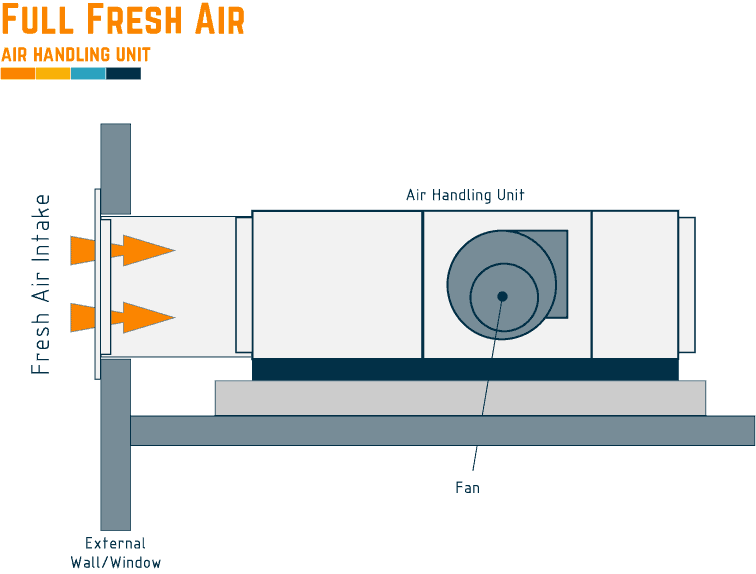
🟧 Air Handling Unit Typical Diagram and Layout [full fresh air]
A full fresh air unit is the simplest form of AHU, where it uses external ambient air to supply the spaces and environments after it has been treated and conditioned.
As with the other types of configurations, it will use, where needed, coils, humidifiers, and controls to do this.
Below is a simple example for this unit, showing the intake for the unit installed within the external wall, bringing air in through a louver, plenum, and ducting.
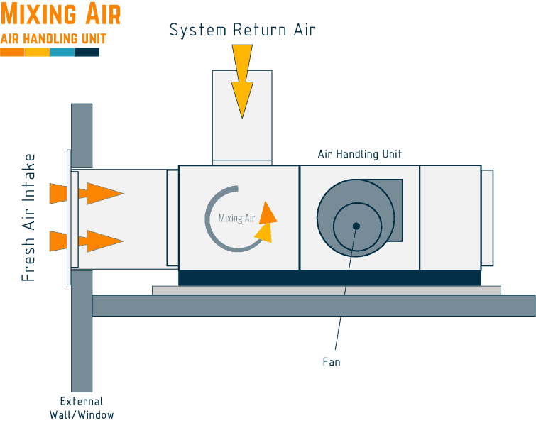
🟧 Air Handling Unit Typical Diagram and Layout [recirculation]
A mixing/recirculation unit uses two air streams to provide air to the AHU. The first will be the fresh air supply, as above, and the second will be the recirculation of air that is brought back from the rooms, spaces, and ceiling voids it serves.
Each air path meets within the ‘mixing box’ where it combines, the return air helping lift or reduce the overall temperature before being sent through the unit and treated, helping maintain energy efficiencies.
Below is a typical air handling unit diagram using a typical return and fresh air duct.
🟩 Air Handling Unit Pipework Diagrams
🟧 Air Handling Unit Schematic Diagram [Typical 2 pipe]
The below shows a typical detail for the pipework configuration, with an explanation below.
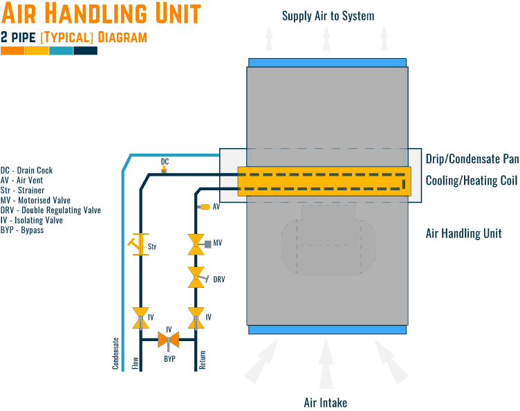
A two-pipe [2] system is the most basic form of design and installation, and the unit will have two possible configurations
- Cooling Only
- Cooling or Heating [depending upon the time of year]
🟨 Cooling Only
A cooling-only unit will only be supplied by chilled water to the coil, usually found where no heating is required throughout the year; for example, in hotter climates and small computer rooms.
🟨 Cooling or Heating
The cooling or heating option is entirely dependent on the time of year; in the summer, we can find that a central chilled water system will feed the two [2] pipe systems and coil, whilst in the winter, it will switch over and be fed by the central heating system.
This is useful if the changes between seasons are short, allowing a clean changeover. If the season changeover is for a more extended period, then there can be complications as the system may be switched to heating for winter, but there is a warm day and need cooling.
🟧 Air Handling Unit Schematic Diagram [Typical 4 pipe]
The below shows a typical detail for the pipework configuration, with an explanation below.
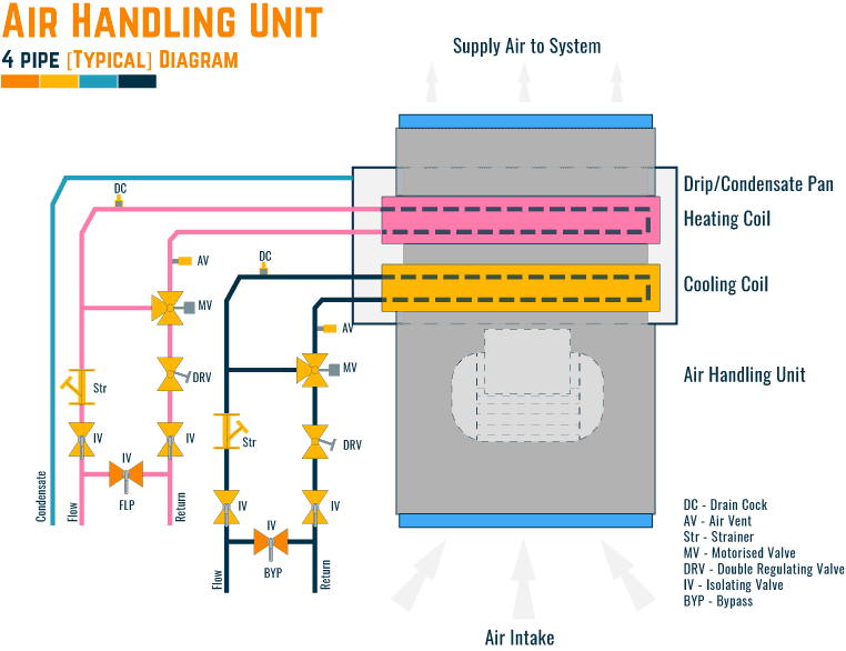
The four [4] pipe system uses two [2] coils within the AHU, one for cooling and one for heating. There are obvious benefits to using this system: no changeovers are required between seasons, and the system will automatically manage the space temperatures as required.
The AHU is connected to the central heating and central chilled water system simultaneously, using the control valves on each system to provide correct temperatures.
🟩 Questions on Air Handling Units
Below we answer some common questions when dealing with an air handling unit.
🟧 Is a Condensate Drain Pipe Required?
Yes, if the cooling coil has been designed where it will produce condensate during the cooling/heating process.
🟧 Do air handling units provide heat?
An air handling unit can provide heat if designed and manufactured with the required components, such as a heating coil [direct expansion or low-temperature hot water].
🟧 Do air handling units have refrigerant?
Yes, an air handling unit with a direct expansion [dx] coil to cool and/or heat will have refrigerant.
The most popular refrigerants used today are R410A, R407C, and R134a.
R22 is still seen but is being phased out due to its environmental impact.
🟧 Do air handling units have filters, and what types are they?
Yes, filters are found within the air handling unit, they are usually split into 2 types primary filters and secondary filters.
As noted earlier in this article, the panel filters remove the larger particles and debris, allowing the secondary filters [bag filters] to be used for the finer ones.
🟧 How many filters are used in an AHU?
The number of filters used within an air handling unit will depend on its configuration and what it is used for.
A straight-through unit, not mixing and serving a single commercial area, would usually have two filters [panel filter + bag filter].
A unit that is mixing and serving an area where filtration is more critical could have four filters [panel filter + bag filter + HEPA filter + return air filter]
🟧 Do air handling units use water or refrigerant?
Air handling units can use either water/refrigerant or a combination of both types.
The type will depend upon the design, which usually depends on the major plant paired with the AHU.
A chilled water system will be paired with a water-cooled or air-cooled chiller and a refrigerant system with an external condenser.
🟧 How does an AHU control humidity?
When the control philosophy for the AHU control system means that the humidity being supplied to the ventilation system is low, a humidifier will be included to help increase it to the overall requirements.
The humidifier will generally be installed downstream of all components of the unit. When required, it will inject steam/mist into the airflow during operation, increasing the overall humidity in the spaces it serves, being monitored by a humidity sensor located within the supply ducting.
🟧 How is temperature controlled in an AHU?
The temperature within an air handling unit will be controlled from a thermostat monitoring the supply air in the following or a combination of the following ways:
- Cooling coil
- Pre-heat coil
- Heating coil
- Fresh air intake,
- Recirculation air,
- Thermal wheel,
🟧 What is AHU Inlet Temperature?
Air handling unit inlet temperature is the temperature of the air that enters the unit before being conditioned, usually from outside [fresh air], or mixed [fresh air/return air].
🟧 What is the difference between AHU and FCU?
🔗for this see our article: 'Fan Coil Unit [FCU] vs Air Handling Unit [AHU]'.
⬛ Related Articles
FAN COIL UNITS | What, Where & How
FIRE DAMPER | Pre-Commissioning Checklist
AHU | Preventative Maintenance Checklist covering Weekly to 3 Years + Download
FIRE DAMPERS | Detailed Guide to Testing
FAN COIL UNIT | Onsite Functional Testing Procedure with Template
FAN COIL UNIT | Week, Month, 6 months, Year & 4 Year Inspections Listed