What is a fan coil unit, what does it do & how does it work?… A fan coil unit is a relatively small piece of equipment that consists of a fan, a coil, and other components, that are used to cool or heat the air recirculating within a room. Some will also add fresh air to the space.
The units are quite common and can be found in most commercial or residential applications.
Typically, to operate in cooling mode, a wall or duct-mounted thermostat will note the space temperature is over setpoint controlling a modulating/on/off valve, the fan will blow air across the chilled water coil that is fed from the building central system, with the cooled conditioned air flowing back into the room, cooling the space.
The cooling coil could also be supplied via a Direct Expansion [Dx] System using refrigerant.
Typically, to operate in heating mode, a wall or duct-mounted thermostat will note the space temperature is below-set point controlling a modulating/on/off valve, the fan will blow air across the heating coil that is fed from the building central system, with the heated conditioned air flowing back into the room, heating the space.
The heating coil could also be an electric type.
They are pretty versatile and inexpensive, having options to be installed in concealed in ceilings, exposed [out of ceiling], underfloor, or mounted vertically against a wall.
🟩 Is a fan coil unit a terminal unit?
A fan coil unit can be considered a terminal unit.
The short definition of a terminal unit is a piece of equipment or device installed within a system to manage and regulate primary air or water from a central source, chiller/AHU, before supplying a conditioned room/space.
🟩 What are the components of a fan coil unit?
An FCU will generally consist of the following components:
- Cased or Uncased [casing around unit]
- Air Intake
- Filter
- Fan
- Cooling Coil [water/dx]
- Heating Coil [water/electric]
- Discharge
- Grille [intake/discharge]
- Speed controller/on/off switch
- Duct/Wall mounted thermostat
- Modulating/on/off valve
![FCU Functional Testing Method Statement Template [MS Word]](https://constructandcommission.com/wp-content/uploads/2023/01/045-PH-Fan-Coil-Unit-Functional-Testing-Template-Sell.webp)
Fan Coil Unit Method Statement [Including the checklist] Template and Instructions in Microsoft Word allowing any editing for full use.
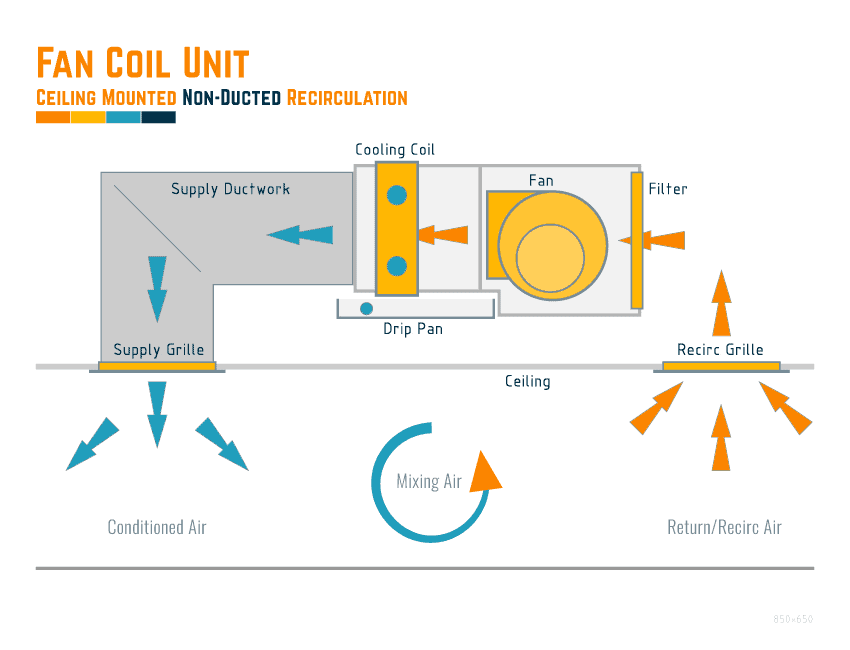
🟩 Fan Coil Unit Diagram [Non-Ducted Recirculation]
The below shows a typical fan coil unit that will use the ceiling as a return/recirculation plenum.
*Note: there could be instances where a fresh air duct is connected to the unit to provide a minimal fresh air volume. This is usually a duct around 100mm in diameter.
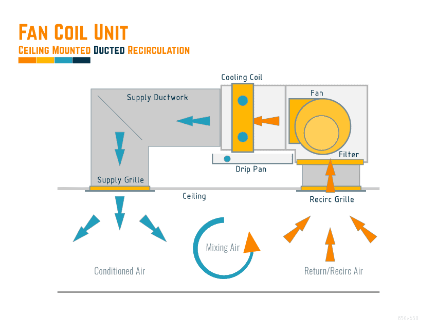
🟩 Fan Coil Unit Diagram [Ducted Recirculation]
Below is a typical detail of a fan coil unit connected to a return/recirculation grille, not using the ceiling as a return/recirculation plenum.
*Note: there could be instances where a fresh air duct is connected to the unit to provide a minimal fresh air volume. This is usually a duct around 100mm in diameter. Diagram has been included later in the article.
🟩 Fan Coil Unit Schematic Diagram [Typical 2 pipe]
The below shows a typical detail for pipework configuration of a two [2] pipe fan coil unit, with an explanation below on the two [2] pipe systems.
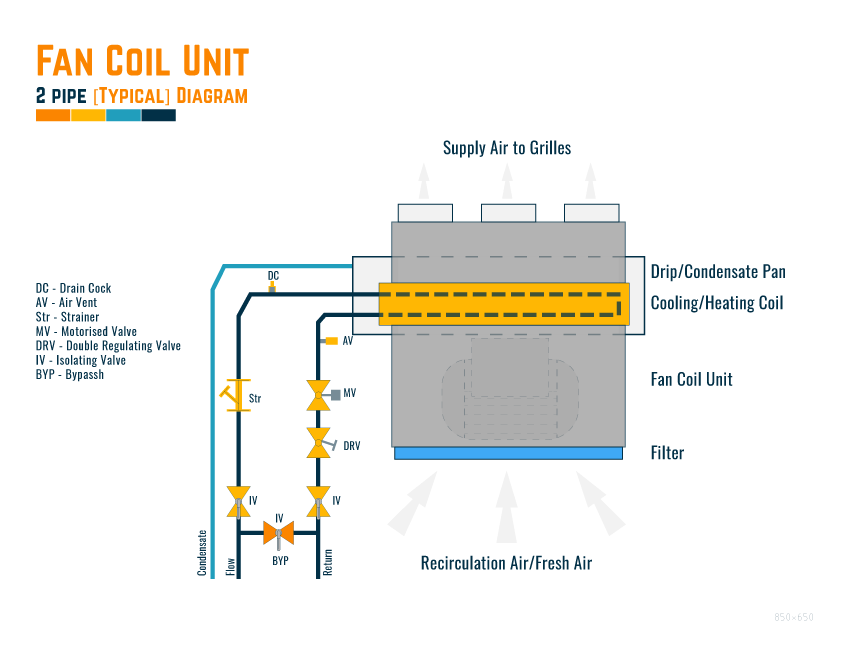
🟩 2 Pipe System
A two-pipe [2] system is the most basic form of design and installation, and the unit will have 3 possible configurations
- Cooling Only
- Heating Only
- Cooling or Heating [depending upon the time of year]
🟧 Cooling Only
A cooling-only unit will only be supplied by chilled water to the coil, and these are usually found installed in spaces where no heating is required throughout the year.
Usually found in hotter climates and small computer/server rooms.
🟧 Heating Only
Similar to the cooling-only system, the unit will be only supplied by hot water to the coil, and these are usually found installed in spaces where no cooling is required throughout the year.
Usually found in colder climates.
🟧 Cooling or Heating
The cooling or heating option is entirely dependent on the time of year, in the summer, the central chilled water system will feed the 2 pipe systems and coil, whilst in the winter, it will switch over and be fed by the central heating system.
This is useful if the changes between seasons are short, allowing a clean change over. If the season change over is over a more extended period, then there can be complications as the system may be switched to heating for winter, but there is a warm day and need cooling.
🟩 Fan Coil Unit Schematic Diagram [Typical 4 pipe]
The below shows a typical detail for the pipework configuration of a four [4] pipe fan coil unit, with an explanation below.
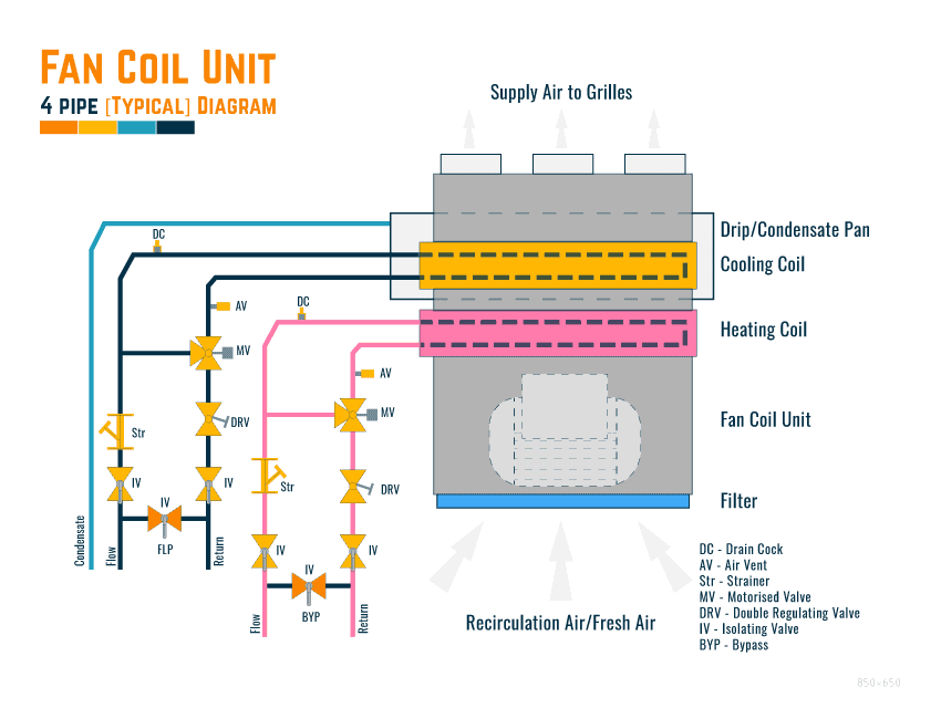
🟩 4 Pipe System
The four [4] pipe system uses two [2] coils in the FCU, one for cooling and one for heating. There are obvious benefits to using this system in that there are no changeovers required between seasons, and the system will automatically manage the space temperatures as required.
The FCU is connected to the central heating and central chilled water system simultaneously, using the control valves on each system to provide correct temperatures.
🟩 Is a Condensate Drain Pipe Required?
In most systems, there will be a requirement to connect the drip pan/condensate tray to condensate pipework that will remove any water generated from the cooling process and dispose of it, usually to drain.
Check your design as, in some instances, there is no need for them, running at higher temperatures, heating only, etc.
🟩 What are the benefits & disadvantages of a fan coil system?
Below details some of the benefits and disadvantages of using a fan coil unit system:
| Advantage | Disadvantage |
|---|---|
| Cost-Effective | If in large spaces, open plan, controls can be affected by other units [units can fight each other] |
| Delivery Time Short | Lots of valves in the ceiling [potential leaks and issues with valves etc.] |
| Easy to Install | Generally, the system will need a separate primary system for providing fresh air. |
| Flexible [especially if there is expected reconfigurations etc. to the floor layouts] | Maintenance can be higher than a central system |
| Easy to Maintain [the unit, but see disadvantages] | Constant access through the ceiling |
| Easy to Replace | |
| Simple Controls, especially individual rooms | |
| They can be efficient if maintained properly. | |
| Spatial Requirements are minimal. |
![Fan Coil Unit Pre-Functional Checklist Template [MS Word] + [MS Excel]](https://constructandcommission.com/wp-content/uploads/2023/07/049d.webp)
Here is our open copy [MS Word] of the FAN COIL UNIT Pre-Functional Checklist, for making life a little easier...
We have also recently formatted this checklist to [MS Excel] and included it as a Bonus for FREE.
So get an MS Word & MS Excel for the same price.
🟩 Do fan coil units provide fresh air?
It will depend on how the system has been designed and configured, but generally, yes fan coil unit can be installed to provide fresh air.
The fresh air can be supplied in 2 ways:
- Directly 100% Full Fresh Air
- Directly or Indirectly [AHU System] Part Fresh Air mixing with Recirculating Air
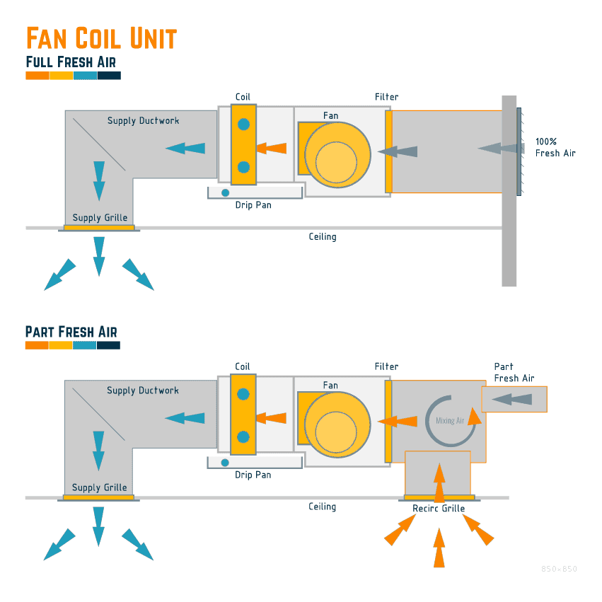
🟧 Direct 100% Full Fresh Air Input
The fan coil unit will be directly connected to a fresh air source, usually via a louvre and ducting from outside. See above graphic.
The unit will then bring in 100% fresh air to the space.
This is not hugely common.
🟧 Part Fresh Air Input
The part fresh air input method is far more common, as seen above in the graphic.
There is a recirculation of air via a grille, and partial fresh air for the space and load is introduced simultaneously, mixing the air before the unit’s fan in a plenum box.
The fresh air is usually supplied via a central AHU system in this instance.
🟩 What types of fan coils are available?
We see that there are generally four [4] types of fan coil units, based upon how they are installed:
- Concealed Horizontal Ceiling Mounted
- Exposed Horizontal Ceiling Mounted
- Vertical Floor/Wall Mounted
- Under Floor Horizontal Mounted
🟧 Concealed Horizontal Ceiling Mounted
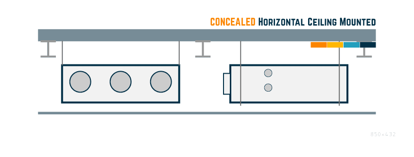
The high-level ceiling-mounted concealed type unit is mounted above a ceiling and then ducted to the space via grilles.
Great if you want to hide the unit for aesthetics or require low noise levels.
🟧 Exposed Horizontal Ceiling Mounted
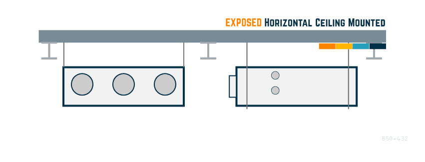
Mounted the same way as the concealed unit, there will be no ceiling showing and exposing the unit.
Grilles can be connected via ductwork, or the units can just blow into the space with no grilles or ducting.
Great if you want to include the building services within the aesthetics of the space [watch the noise levels].
🟧 Vertical Floor/Wall Mounted Unit
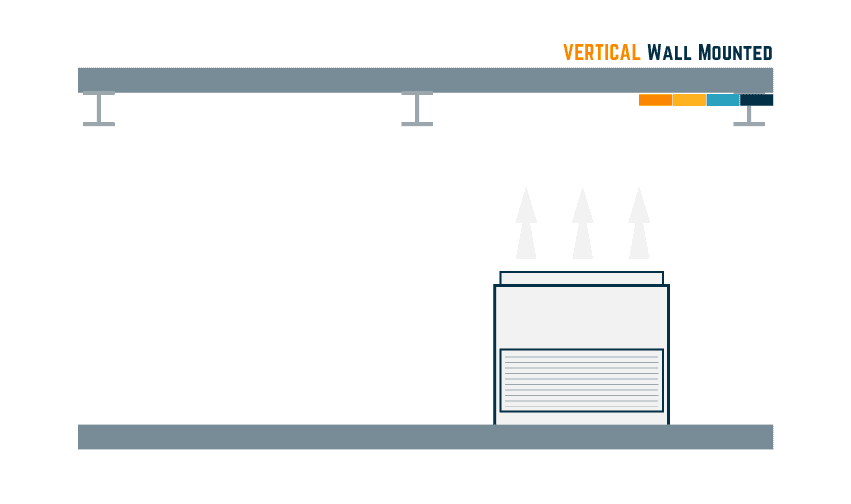
Mounted at a low level on the floor, vertically. The FCU is usually fixed to the wall drawing air from the bottom louver/grille and blowing upwards to condition the space.
Pretty ugly, in our opinion, but if no option…
🟧 Underfloor Horizontal Mounted
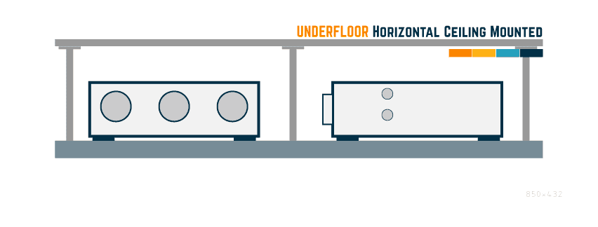
Like the ceiling-mounted unit, the FCU is mounted under the floor, connected to ducting and grilles to recirculate and supply the air to the space.
Quite rare to see this.
🟩 Fan coil unit controls and sequence of operation
The sequence of control requirements of a fan coil system will depend on the type of design employed; obviously, many variables can be discussed, so below focuses upon some standard controls that we have seen on previous projects.

We have been asked several times to create a complete document package covering everything we have uploaded to the site.
So it's taken some time, but here it is....126No. Documents for you to download in Microsoft Word, Microsoft Excel & PDF Formats.
CLICK THE BUY HERE TO SEE/DOWNLOAD A FULL LIST OF DOCUMENTS INCLUDED...
🟩 Two [2] Pipe FCU Control System
🟧 Temperature Control
The conditioned air is controlled by a wall/duct-mounted temperature sensor connected to a controller.
The required space temperature will be set manually and then measured by the sensor. The controller will manage the modulation of the cooling or heating valve, changing the temperature entering the coil to meet the design/spatial requirements.
🟧 Speed Control
The wall-mounted FCU controller will usually have the ability to set the speed locally [3-speed].
- Speed 1 – Low
- Speed 2 – Medium
- Speed 3 – High
- On/Off
The speed selection does not normally allow for it to be automatically varied. Just Low, Medium, or High-Speed selection.
🟧 Time Schedule Control and Setting
To ensure the most efficient system, there will be a requirement to manage the system’s operation via set times when the spaces are occupied. This is usually set at the controller or BMS.
🟧 FCU BMS Points and Alarms
A basic list of BMS points and alarms can be seen below:
| Ref | Type | Reason |
|---|---|---|
| 1 | Space Temperature | Showing the temperature of the space |
| 2 | FCU Run / Stop Status | Showing the status of the fan [if on or off] |
| 3 | FCU Common Alarm | Show an alarm if the unit stops unexpectedly [Overload / Emergency Stop] |
| 4 | Auto/Manual Status | Show if the unit is in Automatic Mode or Manual Mode |
| 5 | Fan On / Off Control | BMS remote control for the fan |
| 6 | Modulating valve control | Controlling of the chilled / heating valve serving the coil |
| 7 | High-Temperature Alarm | Alarm if the temperature of the space goes over the maximum allowable |
| 8 | Time Schedule | Control of the on/off times of the unit |
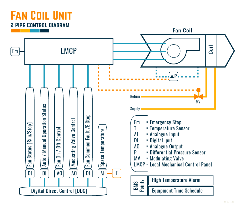
🟧 Two [2] Pipe Control Diagrams
Below is a typical control diagram for a two [2] pipe fan coil unit system.
🟩 Are fan coil units noisy?
From a noise point of view, fan coils are not exceptionally noisy if installed, maintained, set up, and commissioned properly. This includes the air balancing, as that is where much noise will come from if not completed correctly.
The acoustics can be affected by the following:
- Mounting of FCU
- Intake ducting design and routing
- Supply ducting design and routing
- Grille selection
- Air velocity
- Using hard connections to the FCU, ducts and grilles
- Ceiling Construction
🟩 Does a fan coil unit need an electrical disconnect?
Under the following codes, there is a requirement for an emergency stop button/device to be installed and operating on mechanical equipment to allow safe and fast shut down in case of emergency or whilst it is being worked upon. Some of the codes where this is covered are:
- NFPA 70 – National Electrical Code
- NFPA 79 – Electrical Standard for Industrial Machinery
- BSEN 13850 – Safety of machinery. Emergency stop function. Principles for design
🟩 How to install a fan coil unit
We have written an article covering the installation process for ‘FCU | Fan Coil Installation Guideline‘
🟩 How to test and commission a fan coil unit?
Read our article ‘Fan Coil Unit | Onsite Functional Testing Procedure‘ for how to test and commission a fan coil unit with checklists.
🟩 How do you maintain a fan coil unit?
Read our article ‘8 Reasons for Maintaining a Fan Coil Unit‘ for how to maintain a fan coil unit.
⬛ Frequently Asked Questions
⬛ Related Articles
FAN COIL UNIT | Onsite Functional Testing Procedure with Template
FAN COIL UNIT | Installation Guideline
FAN COIL UNIT | Week, Month, 6 months, Year & 4 Year Inspections Listed
FAN COIL UNIT | Pre-Commissioning Checklist
Fan Coil Unit [FCU] vs Air Handling Unit [AHU]