When installing a fixed firefighting gas extinguishing system, under NFPA 2001 and BS EN 15004-1, there is a requirement to complete a Room Integrity/Enclosure Test. This test proves that the space being protected has the required structure and integrity, ensuring that the gas, when released, will be retained and held in the correct density [85%] for [10 minutes], ensuring the fire is cooled/extinguished and not able to reignite.
Below we discuss what room integrity testing is, standards that should be complied with, requirements, and how to complete a standardized test.
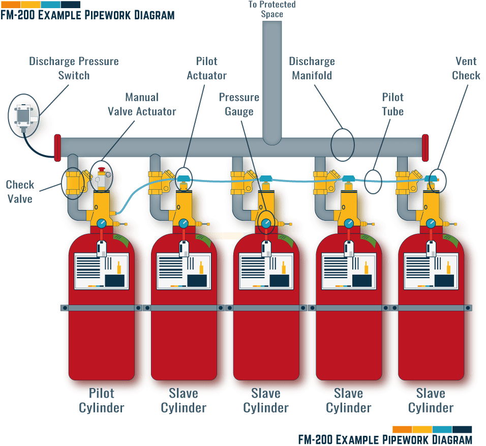
🟩 What is a Fixed Firefighting Gas Extinguishing System?
Fixed gas firefighting extinguishing systems or clean agent systems are fire suppression systems that use the following types of gases to manage and control fire, protecting critical assets that ideally should not be subjected to water during the extinguishing process, such as:
- Data Centers
- Museums
- Archives
- Electrical Rooms
| Extinguishant | Component | Formula |
|---|---|---|
| Novec 1230 [FK-5-1-12] | Dodecafluoro-2-methylpentan-3-one | CF3CF2C(O)CF(CF3)2 |
| NAF-S-III [HCFC Blend A] | Chlorodifluoromethane (HCFC 22) 2, 2 Dichloro-1, 1, 1-Trifluoroethane (HCFC 123) 2 Chloro 1, 1, 1, 2-Tetrafluoromethane Isopropenyl-1Methyl cyclohexene | CF2HCI (82%) CF3CHCI2 (4.75% CF3CHFCI (9.5%) d-limonene (3.75%) |
| Halotron I [HCFC Blend B] | 2,2-dichloro-1,1,1-trifluoroethane | CF3CHCI2, CF4, Ar |
| FE-25 [HFC-125] | Pentafluoroethane | CHF2CF3 |
| FM-200 [HFC-227ea] | Heptafluoropropane | CF3CHFCF3 |
| FE-13 [HFC-23] | Trifluoromethane | CH3F |
| Argotec [IG-01] | Argon | Ar |
| Argonite [IG-55] | Nitrogen (50%) Argon (50%) | N2 Ar |
| N-100 [IG-100] | Nitrogen | N2 |
| Inergen [IG-541] | Nitrogen (52%) Argon (40%) | N2 Ar CO2 |

🟩 Room Integrity Testing Standards
Testing the integrity of the room is usually a code requirement. There are three common standards available for reference, covering the USA, Europe, and the UK:
| Country/Area | Document | Description |
|---|---|---|
| Europe [Eu] | ISO 14520-1 | Gaseous Fire Extinguishing Systems - General Requirements |
| United Kingdom [UK] | BSEN 15004-1 | Fixed Fire Fighting Systems - Gas Extinguishing Systems |
| United States [USA] | NFPA 2001 | Standard on Clean Agent Fire Extinguishing Systems |
| All | Authority Having Jurisdiction [AJH] |
🟩 Room Requirements & Download
To ensure that the protected space is ready for testing, and to give the best chances of success the following checks should be conducted:
| Type | Inspect/Requirement |
|---|---|
| Ceiling | All Penetrations to be complete, with any services and equipment installed. |
| Ceiling | All Holes/Penetrations to be fire stopped and sealed. |
| Ceiling | Any False Ceilings to be installed and complete. |
| Walls | All Penetrations to be complete, with any services and equipment installed. |
| Walls | All Holes/Penetrations to be fire stopped and sealed. |
| Walls | Where Walls meet the ceiling slab should be sealed. |
| Walls | Where Walls meet the floor slab should be sealed. |
| Floor | All Penetrations to be complete, with any services and equipment installed. |
| Floor | Any False Floors should be complete and installed. |
| Floor | All Floor Grilles installed. |
| Doors | All Permanent Doors and frames to be installed. |
| Doors | Doors swing outwards and are self-closing. |
| Doors | If doors are able to be locked from the outside, emergency exit button is installed internally to allow exit. |
| Ductwork | All Dampers [fire/motorized] installed and able to provide the correct seal. |
| Pressure Relief | All Pressure Relief systems are installed with all dampers. |
| Purge System | All Purge Systems are installed with all dampers. |
| Electrical | All trunking and trays are fire stopped including any fire expansion bags installed. |
| General Room Condition | Room is clean and free of debris and dust. |
| General Room Condition | Ensure emergency exit routes around equipment and aisles are clear. |
| General Room Condition | Emergency lighting and directional signs are installed and operational |
| General Room Condition | Emergency/warning signs installed, in line with local codes and regulations, at all entrances to the space, external and internally. |
| System | Alarms, beacons and lights installed and operate immediately upon detection. They shall operate until the system has been reset. |
The above checklist can be downloaded for free

🟩 Who can perform the Testing?
With life safety systems, testing should only be conducted by a responsible person who is qualified, certificated, and experienced
🟩 Room Integrity Testing Procedure/Method Statement
The below details the steps that would be completed to conduct a full Room Integrity Test.
Time for test: approximately 1 hour
🟧 Step 1 – Instruct a Specialist Contractor
The Client, Building Manager, Main/General Contractor should appoint a Specialist Contractor to oversee, complete, and certificate the works.
🟧 Step 2 – Issue and Review Documentation
Specialist contractor to issue all documentation including, testing method, drawings, pre-requisites.
Client representative to review and approve documentation.
![19No. Site Equipment / Maintenance Checklists [MS Word] [MS Excel]](https://constructandcommission.com/wp-content/uploads/2023/05/000f-All-Checklist-Bundle.webp)
We have created this bundle to consolidate all the Equipment Pre-Commissioning and Maintenance Checklists that are available across the site.
The checklists are provided in Microsoft Word and Excel.
🟧 Step 3 – Arrange Testing Date
The Client, Building Manager, Main/General Contractor should provide notice to the Specialist Contractor of when testing can be conducted.
🟧 Step 4 – Room Condition and System Status
The Client, Building Manager, Main/General Contractor prior to testing being conducted and the Specialise Contractor arriving, should complete a full review of the room and its perimeter to ensure all pre-requisites are met.
This would include items such as:
- All walls are complete and sealed where connect to the ceiling and floor slab,
- All permanent doors installed, including any rubber seals,
- All builder’s works holes and fire stopping complete and inspected,
- Ventilation systems are fully complete and installed [Supply, Extract & Purge],
- All fire/motorized dampers installed and able to be set to ‘fire condition’ [closed],
- Ventilation systems to be ‘in fire condition’, this would usually be ‘off’,
- Any openings without dampers are blocked off,
- All other penetrations in walls, ceilings, floors, and fire-stopping complete,
- Drainage pipework, all traps are filled and not open,
- Gas System is isolated.
🟧 Step 5 – Information to Document
Once on-site to complete the testing, the Specialised Contractor will check all room measurements to calculate the protected room volume of the space.
The information to be captured should cover:
- Protect room volume,
- Minimum protected height,
- Normal room operating temperature,
- Weight of the Clean Agent,
- Minimum retention time of the Clean Agent.
🟧 Step 6 – Insert Data & Calculate
From the data collected in Step 5, calculate and add the information into the Room Integrity Testing software.
The testing software will specify the height the gas is to be held at and the retention.
🟧 Step 7 – Setup of Testing Equipment
![[084] Room-Integrity-Test-Equipment](https://constructandcommission.com/wp-content/uploads/2022/01/084-Room-Integrity-Equipment-png.jpg)
After all pre-requisites and checks have been completed, the Specialised Contractor should set up the temporary equipment that is being used, ensuring that there is no leakage around the temporary installation that could affect the testing.
This includes Door frames for cloth and mounting fans, Calibrated door fans, Hose tubing kit, Power supplies etc.
[see below section Room Integrity Testing Kit for a full list of equipment]
🟧 Step 8 – Complete a Positive Pressure Test
Specialist Contractor to switch the fan on, where it will blow air into the protected space creating a positive pressure [around 20pa].
The computer/software will control the fan [pressure] by monitoring the differential across the hoses located on either side of the fan, reading different pressures.
Once all measurements are taken the fan will shut down and the calculation made for leakage.
🟧 Step 9 – Complete Negative Pressure Test
Once the positive test has been completed and all information recorded, the fans will be switched on and reversed to create negative pressure, depressurizing the room.
The computer/software will control the fan [pressure] by monitoring the differential across the hoses located on either side of the fan, reading different pressures.
Once all measurements are taken the fan will shut down and the calculation made for leakage.
🟧 Step 10 – Final Calculation
From the readings the Specialist Contractor will check that the computer/software has calculated the overall hold/retention time of the space, to ensure it complies with the local requirements.
If the retention time is inline then the final report can be completed in Step 11.
If the retention time is not meeting the requirements then an inspection of the space should be completed in line with Step 12.
🟧 Step 11 – Final Report
Once the testing has been complete and the leakage of the space is in line with the local requirements, the Specialized Contractor will issue a report to the Client, Building Manager, Main/General Contractor.
The report should include the following information:
- Enclosure leakage flow characteristics,
- Design concentration of extinguishant,
- Quantity of extinguishant provided,
- Enclosure size and height,
- Protected room volume,
- Height of the highest hazard [Maximum protected height],
- Room temperature [inside/outside],
- Predicted minimum hold time,
- Sketch of protected space under test,
- Test results [computer printout of report].
🟧 Step 12 – If the Test Fails
If the results from the test determine that the integrity of the space will not hold the correct concentration of the gaseous agent, an inspection should be carried out by the Specialist Contractor completing the testing to locate where possible air leakage is occurring.
The following should be checked with the room under pressurized conditions, usually using a smoke pen or smoke sticks:
- All door frames and gaps,
- Where top of wall connection meets the soffit,
- Where the bottom of the wall connection meets the floor,
- All penetrations,
- All fire stopping,
- All ventilation equipment to make sure dampers are closed and not leaking air,
- All pressure relief vents if installed.
Once complete and any issues rectified, the test [from Step 8] should be completed again until the space passes.

🟩 How long does the test take?
If the testing is conducted and there are no issues can take less than 1 hour.
If testing is completed and issues noted, it will depend on how long the remedial works will take and when the contractor can revisit the site to conduct a retest.
🟩 What is Retention Time?.
Retention time is specified by the National Fire Protection Association [NFPA] as 10 minutes.
It is used to ensure that a minimum design concentration [MDC] [85%] of the extinguishing agent can be held at the required minimum protected height [H] in the space for the specified retention period [10 minutes].
All requirements should be checked by the authority having jurisdiction where the project is based.
🟩 Room Integrity Testing Kit
The testing kits used are specialized items of equipment that are tuned to manage minor pressure fluctuations.
The most common kit we have seen across projects is manufactured by Retrotec and consists of:
- Wifi digital gauge
- WiFi dual-channel color touchscreen manometer
- USB cable,
- Cat5 cable,
- USB charging module
- Gauge case
- Magnetic clip
- Gauge calibration verification report
- Calibrated fan (120V/60Hz, 240V/50Hz, or 110V/50Hz)
- Range ring for fan
- Plate for fan
- Blank plugs
- Power cord
- Fan cover
- System calibration verification report
- Aluminum frame
- Cloth for fan, [regular height door]
- Fan crossbar strap for frame
- Case for Frame
- Blower door tubing kit
- Umbilical for fan
- System accessory case

🟩 When to complete a test?
There are three circumstances where testing will be required:
- After new construction works
- After any major modifications to the enclosure
- Every 12 months [for maintenance programme]
🟧 New Construction Works
It is a requirement that after any new gaseous fire extinguishing systems have been installed into the space, the space should have an enclosure integrity test completed to ensure it meets the requirements.
This will also prove peace of mind to the project and end-user that, at the stage of handover, the room’s integrity was adequate for the fire protection system chosen.
🟧 Modifications to the Enclosure
Any modifications made to the enclosure after the initial testing, for example, holes cut to allow additional services to be installed and remedial sealing works have been completed, the enclosure should be retested.
This will be dependent upon the scale of the works.
If minor modifications are made, and it is determined that a test is not required, the works should be documented and stored for future information.
🟧 Inline with a Maintenance Programme of Activities
It is usually industry practice to complete a room integrity test of the protected area every 12 months, under the general maintenance programme for the suppression system.
This is a good idea, as it provides peace of mind and maybe a requirement of the building’s insurance company.
The NFPA and the BS Standard note the following:
🟧 BS EN 15004:
“At least every 12 months, it shall be determined whether boundary penetration or other changes to the protected room have occurred that could affect leakage and extinguishant performance. If this cannot be visually determined, it shall be positively established by repeating the test for enclosure integrity.”
🟧 NFPA 2001:
“The protected enclosure shall be inspected annually or monitored by a documented administrative program for changes in barrier integrity or enclosure dimensions.
Where changes could result in the inability of the enclosure to maintain the clean agent concentration, the conditions shall be corrected.”
⬜ Article References
NFPA 2001 | Standard on Clean Agent Fire Extinguishing Systems
BS EN 15004-1 | Fixed Fire Fighting Systems – Gas Extinguishing Systems
ISO 14520-1 | Gaseous Fire Extinguishing Systems – General Requirements
Wikipedia | 1,1,1,2,3,3,3-Heptafluoropropane
⬛ Related Articles
CLEAN AGENTS | What are they, Types & Benefits
FM200™ SYSTEM | Pipework Pressure & Puff Test Template
FM200™ PIPEWORK | Pre-Commissioning Check List
GASEOUS/FM200 SYSTEM | Functional Testing Template & Download
FM200™ SYSTEM | What is it?
GAS SUPPRESSION / FM 200 SYSTEM | Pre-Functional Checklist