As we know, cooling towers and other evaporative cooling devices rely on the evaporation of water to transfer heat and generate cooling.
Through the evaporative cooling process of the cooling tower, water will leave/evaporate to the atmosphere leaving behind its minerals and dissolved solids, much like when water is distilled, which consists of insoluble salts of calcium, magnesium, chloride, silica, and iron.
Over time, and if not managed, this creates ‘scaling’, which can affect the water quality of the system, increase the risk of corrosion / accelerated replacement of parts, and affect the performance of the equipment, impacting the overall system operation.
Some common issues that would be experienced pointing towards an issue would be:
- Clogging of nozzles
- Accelerated oxidation
- Growth of micro-organisms
- Fouling of the heat exchanger and its surfaces
- Reduction in pipe sizes, by the depositing of scale on the internal surfaces.
To ensure the continued operation of the cooling tower systems, water must be replenished into the system as it evaporates and its quality controlled.
Generally, 3 different systems will be used to manage the process, and will be discussed further in this article:
- Make-up water system
- Water treatment systems
- Bleed / Blowdown system
Codes / Guides & Standards
For the above systems, and to ensure that the requirements are met regarding, water quality, water discharge, operational needs, certification, etc, there are certain codes, guides, and standards that have been written to reference.
- ASHRAE Fundamentals
- ASHRAE Systems
- ASHRAE Applications
- CTI Standards and guidelines
- Local Codes and Regulations
[link for ASHRAE | CTI | for local codes refer to your area and country]
What is Cooling Tower Make Up Water?
Makeup water [fresh water or if the jurisdiction allows – grey/potable water], is introduced into the cooling tower water basin to replenish any water that is lost through the evaporation, drift, and bleed/blowdown process of the tower.
Makeup Water Control
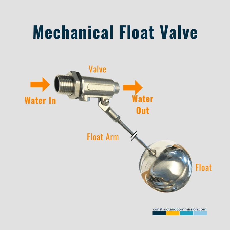
The way in which the introduction of the water is controlled is usually simple.
The water is continually fed into the cooling tower basin by a mechanical float valve, which will maintain the required water level for the system to operate and in line with the manufacturer’s recommendations.
Make-Up Water System Components
The components that would usually be needed to allow the system to operate would be:
- Mechanical Float Valve
- Range of pipework
- Water tank [usually gravity fed in hotter climates]
- Bladder tank [used in freezing climates]
- Booster Pump [depending on location of water tank]
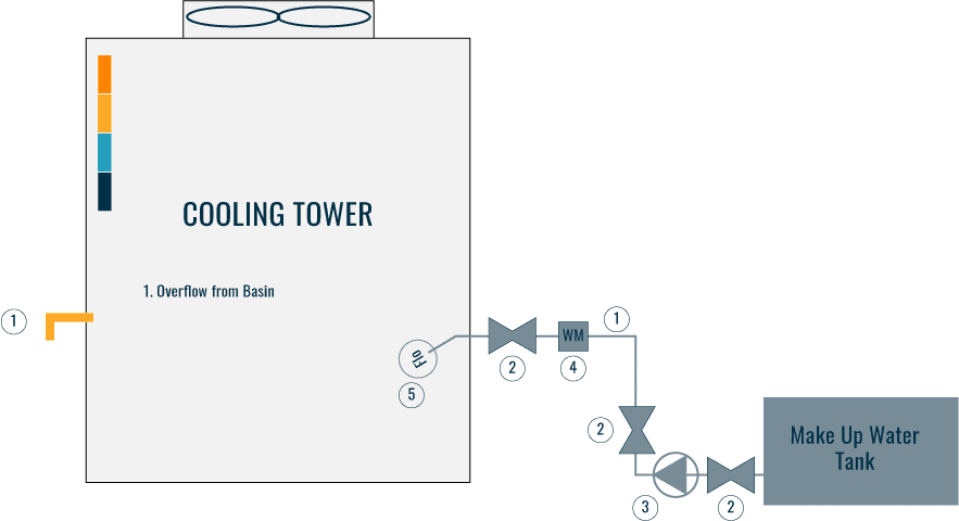
Cooling Tower Makeup Water Piping Layout
For information on the pipework configuration for the system see our article ‘Cooling Tower Piping Layout and Diagrams [Makeup Water]’
Make-up Water Design Considerations
General Considerations
When looking at the design of the Makeup water system the following should be considered:
- Flow rate required
- General system inaccuracies of an open loop system with float valves
- Outdoor design conditions
- Allowable system runtimes
- Resilience/security of the water supply
- Make up water quality
The makeup water system must be able to replenish the water losses of the cooling tower system during normal operation, with the losses coming from:
- Evaporative losses and
- Drift losses
The system will also need to cater to the concurrent operation of the cooling towers during any blowdown/bleed operation.
Failure to do so will result in air ingress into the condensing water circuit which, if bad enough, can lead to a catastrophic failure of the system.
Loads, Wind, Pump Operations
It should be noted that at different loads, wind direction, and condenser water pump operations, the level of the system can fluctuate substantially, sometimes up to 10cm [4 inches].
The makeup water should be designed to cater to these levels of inaccuracies, with the design incorporating balancing tanks, secondary smaller float valves, reservoirs, and other devices.
Water Tank Size Considerations
Consideration should be given to the size of the water storage tank that is being used to feed the makeup water system.
Jockey or lift pump operations are usually constrained by the number of starts per hour [s/hr] that the manufacturer allows, to protect them from overheating.
The water tank sizes should be designed to store enough water so that the pump does not have to operate at a higher hourly rate than the manufacturer recommends.
Water Supply / Locations
Water supplies where it is observed that may be unreliable or sporadic, the designer should consider a larger onsite storage solution to mitigate the risk.
Buildings, where poor water quality has been noted, may consider water treatment and filtration options to improve the water quality for cooling tower use prior to entering the cooling tower system.
Similarly, at different site altitudes, the heat of water vaporization may vary significantly and therefore the amount of water required for the same amount of heat would vary.
Cooling Tower Cycles of Concentration
As noted above, as the water evaporates from the cooling tower system during the cooling process, solids are left behind.
These solids are usually referred to as ‘TDS’ [Total Dissolved Solids].
To manage the build-up of these solids, water is ‘blown’ to drain, and make-up water is introduced to replace what has been discharged, keeping the system ‘topped up’ and within the water quality needs of the system.
A Cycle of Concentration / Concentration Ratio for a cooling tower/condenser water system can be described as “the ratio of dissolved solids calculated within the process/system water vs that calculated within the make-up water”.
If the process/system water has 5 times the TDS concentration than the make-up water, the Cycles are 5.
The lower the Cycle number, the more frequent the blowdown, increasing the water usage and chemicals needed to manage the system.
To reduce the water usage [reducing the blowdown water and make-up water] in the cooling tower, the cycle number should be increased.
Cycles of Concentration Design Considerations
The Cycle of Concentration for each system should be designed accordingly to the local makeup water supply impurities level and the maximum equipment allowable impurities level for safe operation.
Usual design parameters for COC would be the following
- between 3 in hard water locations,
- 6 in soft water locations; but
- some designs may operate to a COC of 20 effectives, by the means of water filtration and polishing plant.
Some jurisdictions may have stricter COC limits for water resources preservation and should be checked by the designer.
Cycle of Concentration Calculation
The calculation to understand the COC within a system would be the following:
CyclesOfConcentration = CoolingTowerConcentration / MakeupWaterConcentration
Cooling Tower Chemical Water Treatment
To control and minimize the risk of scaling, microbiological fouling, corrosion, downtime, and accelerated replacement of parts and equipment a water treatment system would generally be needed to operate with the Condenser/Cooling Tower System.
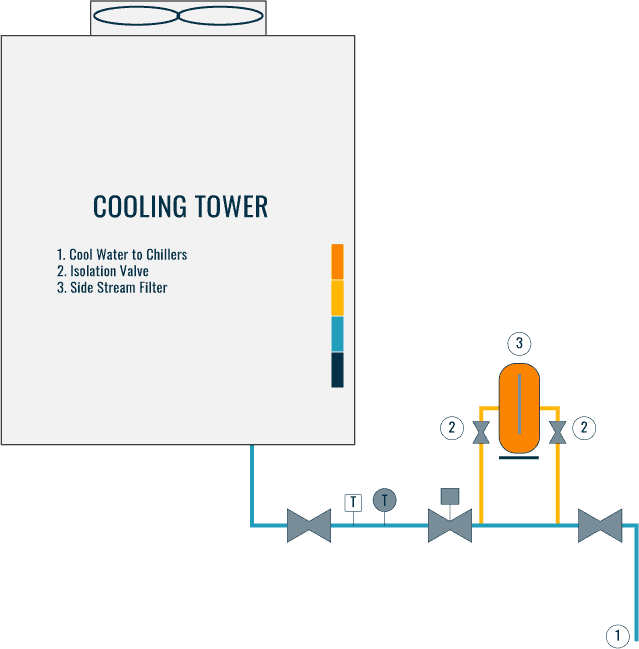
Water quality control devices and equipment can be installed full stream or side stream to the tower water circulation system.
Full Stream System vs Side Stream System
A full stream system, also known as an inline system, treats or filters 100% of the water flow.
A side stream system will divert some flow for processing, usually 5%-10% of the total design flowrate.
Which to choose?
The choice of a full stream or a side stream system design is generally based upon space limitation and the expected level of contaminant ingress.
For example, in an area with more common sand and dust storms, it would be more beneficial to design and install a full stream system.
Who would design the Water Treatment System?
A trained and qualified water treatment specialist should be employed to evaluate and specify the requirements of the system considering the expected water quality of the system, cycles of concentration, blowdown, makeup water, local/regional codes, and manufacturers’ specifications.
Cooling Tower Water Quality Parameters and Control
Check with the equipment manufacturer and local code requirements, but typically, a cooling tower shall be kept within the following water quality operating parameters:
| Parameter | General Criteria | Usual Control Method |
| Heterotrophic colony count | ≤ 100,000 cfu/mL | Chemical Dosing |
| Total legionella count | ≤ 10 cfu/mL | Chemical Dosing |
| Conductivity | ≤ 1,500 μS/cm | Chemical Dosing, Bleed/Blow-down |
| Total dissolved solids | ≤ 1,000 ppm | Chemical Dosing, Bleed/Blow-down |
| Suspended solids | ≤ 150 ppm | Bleed/Blow-down |
| Calcium hardness | ≤ 500 ppm | Bleed/Blow-down |
| pH | 7 – 10 | Chemical Dosing, Bleed/Blow-down |
| Total alkalinity | 80 – 500 ppm | Chemical Dosing, Bleed/Blow-down |
| Oxidizing biocide | Per oxidizing biocide product recommendation and equipment allowance | Chemical Dosing |
| Inhibitor level | Per rust inhibitor product recommendation and equipment allowance | Chemical Dosing |
| Temperature | Suitable for design application | N/A |
| Chloride | ≤ 200 mg/L | Chemical Dosing, Bleed/Blow-down |
| Sulphate | ≤ 200 mg/L | Chemical Dosing, Bleed/Blow-down |
| Iron | ≤ 1.0 mg/L | Chemical Dosing, Bleed/Blow-down |
| Residual Chlorine | ≤ 0.3 ppm | Chemical Dosing, Bleed/Blow-down |
Dosing Chemicals
Chemicals that can be used to control the water quality within the cooling tower/condenser water system are listed in the table below. It should be noted that due to the geographical limitations and requirements, the specific chemicals of choice for a project should be tailored to the local site and selected by a water treatment specialist.
| Chemical Function | Description |
| Antiscalant | There are two main types of scale inhibitors: Threshold inhibition chemicals preventing the initial formation of scale, and Scale conditioners which react turning the scale into something more like sludge than a hard scale, which can then be carried away by the flowing water and removed by the filtration system or blowdown. |
| Dispersants | Dispersants are chemicals used to prevent the lumping and binding together of any suspended solids, organic matter, and dissolved solids which may clog up the equipment such as heat exchangers or cooling tower nozzles. |
| Detergents | Detergents are used to clean organic and inorganic films such as oils from the surfaces of the pipework and other equipment such as the heat exchangers to maintain the heat transfer efficiency. |
| Corrosion inhibitors | Corrosion inhibitors protect the equipment and material from corrosion. This is competed by reducing the corrosive agent into a milder form. |
| Scavengers | Scavenger chemicals are used to remove dissolved gases such as oxygen that may oxidize and or allow microbes to grow. |
| Biocides | Biocides are introduced to help manage any algae, which is a nutrient for bacterial growth. Algae can encourage corrosion and foul equipment. Fungi can foul equipment and bacteria which can be pathogenic, chemotrophic and consumes the ferrous metals generating acids as a by-product. The biocide must be tailored to the cultures present and will require regular adjustments and tunning as a particular biocide that is used to control the primary culture may allow a secondary culture to develop and take its place. Oxidizing biocides are generally fast-acting and kill all micro-organisms, including bacteria, algae, fungi, and yeasts. However, they degrade rapidly, especially under heat and sunlight, and is corrosive as most are acidic. Non-oxidizing biocides are slower and are used to target a specific metabolic or reproductive process of the microorganism. As non-oxidizing chemicals, these biocides degrade at a slower rate and therefore they retain protection for a much longer period. |
| Passivation | Usually used where galvanized systems are installed, a passivation agent is introduced into the system which creates a coating and film on the material and equipment which isolates them from the circulating water. The coating prevents the corrosion of the material, and at the same time prevents leaching into the water such as copper and iron particles. |
| Softener | Water softening chemicals can be added to the makeup water supply to reduce its hardness and therefore the likelihood of scale formation within the cooling tower systems. |
| Acidity alkalinity control | Many scaling compounds such as calcium carbonate and calcium phosphate can be controlled as the solubility of its salts increases with increased acidity. However, increasing acidity may increase the corrosion rate and certain microorganisms may have a preferred PH level. Acidity alkalinity control is generally by the additions of diluted sulphuric acid, alternatives are also used to tailor to site conditions. |
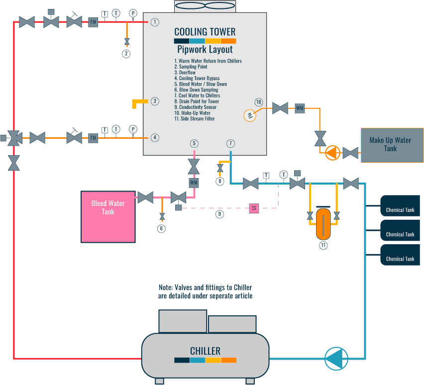
Chemical Dosing Controls
The chemical dosing equipment is usually placed downstream of the cooling towers as the cooling towers is the location where the makeup water will enter the system and the cooling tower will pick up the contaminants.
Sensors for water quality should be located upstream of the cooling towers to ensure that the chemicals have been fully mixed and that some time has elapsed to allow it to work to get a meaningful reading.
Chemical for the systems can be controlled by the following means:
- Time Clock [constant bleed system]
- Interlock with the blowdown valve [constant bleed / blowdown system]
- Water quality sensors [constant bleed / blowdown system]
Sacrificial Metal Oxidation Protection
What is sacrificial metal oxidation protection?
To protect the system and its materials from corrosion [steel pipework and coils etc] sacrificial metals are installed that is a more reactive metal. The protection can be achieved by mean of fitting zinc bracelets at regular intervals along the pipework and installing zinc blocks within the shell and tube heat exchangers.
Another method may be to coat the surfaces with galvanized zinc paint, hot-dipped or electroplated.
The sacrificial metals work on the principle of galvanic corrosion where the anodic metal [zinc] will corrode before the cathodic metal [steel].
Sacrificial metals are required to be replaced from time to time and the chemical dosing system should be designed to control its salts.
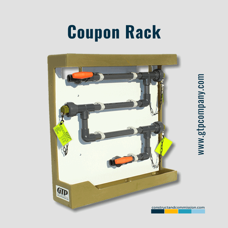
Corrosion Coupons/Coupon Rack
There are many aspects of the water quality treatment process that could be determined by chemical analysis of the circulating water. However, this does not show the actual resultant action of the chemicals and water on the internal surfaces of the equipment and pipework.
Obviously, it is unrealistic to shut down and cut open the water system to witness and understand the scaling or measure the corrosion rates that may have occurred during operation.
If want to read more on Coupon Racks see our article 'CORROSION COUPONS | and Coupon Rack'
To help understand the rate of scaling and corrosion, corrosion coupons are often fitted to the system. These are calibrated pre weighted metal strips “coupons” or “tabs” consisting of the metals in contact with the cooling tower water and are generally ½ inch (12.5 mm) wide, 3 inch (75 mm) in length, and 1/16 inch (1.6 mm) thick as per the ASTM standards.
Usual Coupons deployed in a cooling tower system are:
- Aluminium alloys
- Low carbon steel
- Copper Alloys
- Stainless steel
The coupons are removed periodically [30, 60, 90 & 120 days] to be inspected, dried, and weighed against its original calibrated mass, to determine corrosion rate. The corrosion rate should stabilize to a certain level over a period of 30 days or more.
Cooling Tower Filtration Systems and Other Systems
During the day-to-day operation of an ‘Open’ cooling tower system it will naturally introduce particulates and debris into the system via the following means:
- Location of installation [dirty/dusty environment].
- Weather [rain washing particulates into the tower].
- Ambient/external air being drawn through the cooling tower.
- Debris/corrosion from the internal surfaces of the system.
- Makeup water/suspended solids.
To manage this and keep the system clean, filtration systems and equipment will be used that can consist of the following items:
| Device | Target Contaminants | Notes |
| Strainers | Large solids | Strainers are designed to prevent the ingress of large solids which may damage the pumps or clog up heat exchangers. Therefore, strainers can be selected typically from fine Ø1mm to protect brazed plate heat exchangers to coarse at Ø8mm to protect pump impellers. Consult actual equipment manufacturer. Generally, it is desirable to have a coarser strainer to reduce servicing intervals. |
| Cartridge filters | Minerals in makeup water | Cartridge filters are disposable or washable media filters that can filter down to 1 micron if required. Due to the dust collecting nature of cooling towers, cartridge filters are generally only used to control make-up water quality which has excessive minerals. |
| Sand filters | Dust and suspended solids | Sand filters are used to remove particles usually down to 20 microns at an expected ~80% effectiveness. It can filter finer particles with a corresponding increase in pressure drop. Soiled sand filters would have significantly higher pressure drops and thus these are not as suitable for full stream operation. Sand filters are generally equipped with backwash systems that would regenerate the media and this will contribute to additional bleed water usage. |
| Cyclone Filters | suspended solids | The cyclone filter is also known as the centrifugal filter, hurricane filter, and other similar names. It works on the principle of the moving fluid being spun around and the heavier than water particles being separated by centrifugal force. Cyclone filters are used to remove particles down to 5 microns at around ~50% effectiveness depending on the operating velocity. Separated particles are left to sink and are collected at the bottom and therefore do not significantly increase in pressure drop when soiled as such it is suitable for full stream applications. This can be cleared by discharging the filter both automatically and manually, and this will contribute to additional bleed water usage. |
| Air and Dirt Separator | Dust and suspended solids, air, and metallic particles | Air and dirt separators are used to remove very fine suspended solids such as dust and dissolved gases by artificially creating a low-pressure volume by venturi effect to encourage the dissolved gasses to escape. The gases are given time to escape in a chamber in which the water velocity is lower and as such it also allows very fine and light dust to settle. As such this configuration removes both dust and air from the system and is very common to equip air and dirt separators with magnetic catches to catch ferrous particles and automatic air vents to allow the gasses to escape. |
| Reverse Osmosis Water Treatment | Dissolved solids | Reverse osmosis systems can remove dissolved solids such as salts, these are normally only removable by bleed/blowdown and thus with a reverse osmosis system, system Cycles of Concentration [COC] as high as 20 can be achieved (COC, as circulated, will never exceed the ~6 value or manufacturer acceptable limit). |
| Electronic Algae Control system | Algae | Algae is naturally buoyant and is equipped with a cellular membrane that resists chemical biocides. The electronic Algae Control system uses ultrasonic waves to physically destroy the formation of algae. |
| Ozone Generator | Microbes | Ozone is a powerful oxidization agent, and it deactivates and kills microorganisms by oxidizing their organic matter and rupturing the cell walls. Ozone is generated by an electric arc generator and has a very short life. As a powerful oxidization agent, it may potentially be corrosive to the material and equipment and therefore must be balanced out with other treatment options when deployed. |
| Ultraviolet Lamp | Bacteria | Ultraviolet Lamps can be used to inactivate bacteria through the denaturing of their DNA. To work, it must be able to penetrate the cellular structure of the bacteria, and this means that it cannot be shadowed by a dust particle and therefore is best deployed after filtration. |
| Copper and Silver Ionisation | Microbes | The Copper and Silver Ionisation system generates free copper and silver ions. These ions kill microorganisms by oxidation it. However, such a system is not suitable for use with a system using ferrous and aluminum components as these ions will cause galvanic corrosion. Thus, this is limited more to copper/titanium heat exchangers and polymer pipework. The former may be cost-prohibitive. |
| Cathodic Protection | Corrosion of materials | Working on the principle of galvanic corrosion where negatively charged metals will corrode less than positively charged metals, an electrical current is inserted into the metalwork, to make it negatively charged. |
Cooling Tower Blowdown/Bleed Water System
To manage the water quality, build-up of scaling, and total dissolved solids [TDS] within the condenser water system there will be a requirement to ‘blowdown or bleed off’ the water from the tower basin to allow, at the same time, replenishment with clean fresh water from the Makeup water system thus managing the quality of water.
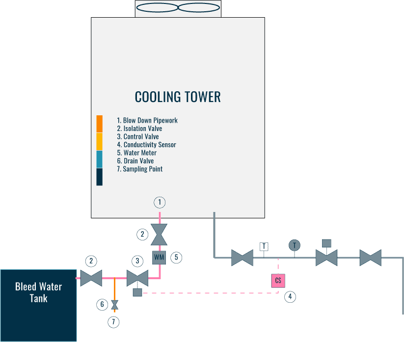
Blowdown and Bleed Water Control
A blow-down system is traditionally set and activated according to a timer, with the bleed system being set to be continuously open for the design bleed rate irrespective of use.
Obviously, constantly draining the system is wasteful of water and today the newer blowdown systems will generally operate with water quality/conductivity sensor activating the blowdown function when a certain set limit is reached.
When activated, the system will then be run for a specified and set period or until the sensor reading reaches acceptable levels. Similarly, for bleed systems, the bleed valve can be modulated to maintain a water quality sensor reading such as TDS.
The placement of the bleed or blowdown valve should be upstream of the makeup water connection point to prevent the new makeup water from being bleed away immediately without being able to be fully mixed.
Bleed or blowdown water may or may not require to be neutralized for the chemicals used for water quality and therefore may need to be captured in a bleed water tank. In some jurisdictions, this water can be used for irrigation, cleaning, and toilet flushing applications. Check with local codes and chemical specialists for requirements.
Example of Calculations
Pure drain and blowdown systems are uncommon as after every blowdown, the system needs to be purged of air which can be challenging while the continuous bleed systems will bleed significantly more water than designed due to the various inefficiencies of the mixing and the distance between the of the makeup water point and the bleed point. The following examples are shown as the two extreme ends of the design and normal operation is generally in-between.
How to calculate Make-Up water requirements?
Make-up water must cater for 3 parts, evaporation losses, drift losses, and blowdown/bleed. Historically, evaporation losses and drift losses have been calculated as a percentage of the circulation rate. While this rule of thumb is simple, it is only valid for a traditional design of a 5°C temperature difference for evaporation losses, at different temperature delta regimes, this is inaccurate.
Evaporative Losses can be calculated by the latent heat of evaporation of water which at atmospheric pressure at sea level is approximately 2260 kJ/kg. Thus, if a cooling tower needs to reject 1000 kW of heat, the vaporization would be:
1000kW = 1000kJ/s
(1000kJ/s) / (2260kJkg = 0.442kg/s
As the density of water is approximately 1000 kg/m3, or ~1 kg/L, this would be 0.442 L/s of evaporation.
Drift losses are based on the cooling tower manufacturer data and are normally based on circulation rate. This is usually between 0.5% to 0.02% of the water circulation rate and thus is dependent on the local wind conditions, drift eliminator design in the cooling tower, and building geometries. At sea level, the specific heat capacity of water is approximately 4.18 kJ/kg and assuming a design temperature difference of 5°C (K) and a drift loss of 0.05%. A cooling tower needs to reject 1000 kW of heat, the drift loss would be:
(1000 kJ/s) / (4.18 kJ / kgK × 5K) ×0.05% = 47.84 kg/s × 0.05% = 0.0239 kg/s
Blowdown or bleed is calculated by the cycle of concentration. The concentration of the cooling tower water equal to the total mass of contaminates contributed by the water that was evaporated drifted away, and entered the system via blowdown.
Cycles of concentration (COC) is a measure of how much contamination is within the water and in essence, it is the ratio of the makeup water contamination level compared to the body of water contamination level (say cooling tower). With this definition, the cycle of concentration is analogous to:
Cycles of Concentration = Cooling Tower Concentration / Makeup Water Concentration
Example 1: Gravity feed make up water system with drain and fill blowdown
This example will be of the following design parameters:
- 1000 kW heat rejection cooling towers
- Condensing water system volume is 20 m3 which 50% is drainable, to keep all the pump’s volutes submerged.
- Makeup water tank above cooling tower and feed cooling tower by float valves
- Bleed system is by TDS concentration at 1000 ppm and makeup water is 166 ppm. This will give a COC of 6. The blowdown would be by timer for 10 minutes
- Lift/jockey pumps have a minimum runtime of 5 minutes, and 2 max starts every hour.
From the previous calculations, we know that the:
EvaporationLosses = 0.442kg/s
DriftLosses = 0.0239kg/s
With the drain starting at TDS concentration at 1000 PPM and a makup water at 500 PPM; and an effective drainable volume of 50%. We know that the final mixed concentration to be:
1000ppm × (100%-50%) +166ppm × 50% = 583ppm
With a COC of 6, 6 times makeup volume is required at 50% of 20 m3, this will therefore be:
MakeupVolumeBeforeBlowdown = (6 - 1) x 10m3 = 50m3
With a sanity check:
(583ppm x 20m3 + 166ppm x 50m3) / (20m3) = 998ppm
Which is close enough. The normal operating water consumption rate is evaporation plus drift:
0.442kg/s + 0.0239kg/s = 0.466kg/s
This will work out to a time between blowdown as:
(50m3 x 999kg/m3) / (0.466kg/s) = 107,189 seconds - 29 hours 46 minutes
In normal operation, the lift pump can operate twice every hour, or once every 30 minutes. In that time, the cooling tower would consume:
30 minutes x 60 seconds/minute x 0.466kg/s = 838.8kg = 838.8L
Design for the worse case, the cooling tower is off, and the low water level triggers the pump to run. The pump must be able to operate its minimum runtime of 5 mins and therefore:
(838.8L) / (5 minutes x 60 seconds/minute) = 2.8l/s
As per the design parameter, the blowdown of 10 m3 and therefore makeup happens over 10 minutes, then the makeup rate would have to be:
(10m3 x 1000 l/m3) / (10 minutes x 60 seconds/minute) = 16.7l/s
The storage tank of 838.8L with a makeup pump flowrate of 2.8 L/s will not be able to fill 10 m3 in 10 minutes as 2.8 L/s < 16.7 L/s and the capacity is insufficient. At this point, the designer will have to increase the storage tank size to compensate. If keeping the pump rate, the tank will have to be:
(16.7l/s - 2.8l/s) x 10 minutes x 60 seconds/minute = 8340 litres
This will add significant weight to the building and therefore realistically, a tank size of 4 m3 will be more suitable. This would mean that the pump would need to be:
(10,000L - 4000L) / (10 minutes x 60 seconds/minute) = 10l/s
Checking pump run time again:
(3500L) / (10l/s) = 350 seconds = 5 minutes 50 seconds
And therefore, this selection is valid, the gravity makeup tank should be 4m3 and the makeup pump should be sized for 16.7 L/s. Supply pressure and pressure rating to suit the building height.
Example 2: Booster feed make up water system with continuous bleed
This example will be of the following design parameters:
- 1000 kW heat rejection cooling towers
- Condensing water system volume is 20 m3 which 50% is drainable, to keep all the pump’s volutes submerged.
- Makeup water tank above cooling tower and feed cooling tower by float valves
- Bleed system is by TDS concentration at 1000 ppm and makeup water is 166 ppm. This will give a COC of 6. The blowdown would be by timer for 10 minutes
- Lift/jockey pumps have a minimum runtime of 5 minutes, and 2 max starts every hour.
From the previous calculations, we know that the:
EvaporationLosses = 0.442kg/s
DriftLosses = 0.0239kg/s
In a continuous bleed system, the amount of water where all the contaminates can reside is by the drift which takes some of the contaminates away and the makeup water that equal the blowdown., this becomes:
COC = (EvaporationLoss + DriftLoss + Bleed) / (DriftLoss + Bleed)
Bleed = (EvaporationLosses - [(COC - 1) x DriftLosses]) / ((COC - 1))
Thus, assuming the same 1000 kW heat rejection system with a system design COC of 6, the blowdown required would be:
Bleed = (0.442kg/s-[(6-1)x0.239kg/s]) / (6-1) = 0.0645kg/s
Note that the system may be shut down and drained as a full blowdown or water continuously released as bleed during cooling tower operation. A shut down and release being more effective but disruptive while a continuous bleed is less effective and therefore will use more water. Which method is dependent on the operational requirements of the cooling tower and the code requirements Usually a slow bleed system will be accounted for by a safety factor and the fact that the cooling tower is not going to be operating at full capacity all the time? Assuming a continuous bleed system that is 100% effective, thus for this system, the minimum makeup water requirement is:
Evaporation + Drift + Blowdown = 0.442kg/s + 0.0239kg/s + 0.0645kg/s = 0.53kg/s
As the density of water is approximately 998 kg/m3 at sea level and habitable outdoor temperatures, or ~1 kg/L, this would be 0.53 L/s for make-up water. Assuming some maxing inefficiencies and safety factors for a total of 25%.
0.53l/s x 125 = 0.663l/s
Therefore, the makeup pump should be sized for a minimum of 0.663 L/s with a corresponding bladder tank and supply pressure suitable for the building.
⬛ Related Articles
COOLING TOWER | Preventative Maintenance Inspections
COOLING TOWER | Inspecting & Cleaning Overview
COOLING TOWERS | All 38 components explained
COOLING TOWER | What is a Sweeper System?
COOLING TOWER | Types of Towers and Ponds
COOLING TOWER | Piping Layout and Diagrams