Upon completion of any new CRAC [computer room air conditioning] Unit installation or modifications to an existing unit, there will be a requirement to complete a functional test to ensure that the equipment operates in line with the design requirements before being put into permanent operation.
To cover the works, we will run through the following items to ensure that the testing and commissioning is conducted correctly:
- Who will complete and validate the testing
- Health and safety
- Permit to work systems
- Documentation that is required
- Acceptance criteria and tolerances
- System Integrations
- Testing equipment and tools to be used
- Inspections, sign off and defect management
- System functional testing
- Full testing template
If you want to understand more on CRAC Units and how they work see our article 'CRAC UNITS | What are they?'
What types of tests should be completed?
The following list details testing that can be completed on the CRAC Unit; your project may be slightly different, but these are pretty common:
- Equipment setting checks
- External direct expansion [Dx] unit checks
- Condensate tray/pipework tests
- Operation of the sump pump
- Sensor calibrations
- Checking running currents of fans
- Fan speed measurement
- Airflow measurement
- Operation of electrical automatic transfer switch [ATS]
- Sound level measurement
- BMS points and alarms
- CRAC unit sensor failures
- Quick start functions
- Humidifier operation
- Reheat coil operation
- Group control operation and integration
- Cooling capacity verification
- CRAC fan speed stability

Who will complete and validate the system testing?
Due to the criticality of the system and method of test, only engineers who are qualified and experienced in the works should conduct the testing.
Most commonly, the manufacturer’s internal engineering team will ensure they are setting up the equipment in line with their requirements and operational needs, ensuring all warranties are maintained.
Witnessing, where required, would be the responsibility of the client’s representative, usually, the Commissioning Provider or Facility Management Department, who should make themselves available when needed.
| Task | Responsible |
|---|---|
| Writing and issuing testing documentaiton | General Contractor |
| Approval of documentation | Commissioning Manager |
| Supplying all equipment and instruments | General Contractor, Vendor |
| Arranging resources | General Contractor |
| Coordinating and managing testing | General Contractor |
| Self testing | General Contractor, Vendor |
| Client witness testing | Facilities, CxA, General Contractor, Vendor |

Health & safety
Health and safety should be managed during these works due to the completed tasks.
Areas to consider would be:
- Qualifications of operative
- Potential working at height
- Working on/with live electrical systems
- Working on/with refrigerant systems
- Working with moving parts [fans, dampers etc]

Permit to work
Permit to work documents should be detailed and included to ensure that the relevant requirements to allow functional testing of the equipment are met; items to have would be:
- General access to the site
- Access to specific space where the internal and external equipment is located and,
- Access to surrounding areas [data hall, switch room, ups room], if the internal unit is located in a separate corridor,
- Working on electrical systems,
- Working on refrigerant systems,
- Life safety system isolations,
- System integrations

Documentation required
Before any testing starts, there will be a need for specific documentation to be available such as:
- Completed and approved delivery, storage, and installation checklist,
- Approved material submission,
- Approved manufacturer’s drawings showing detailed information on the equipment,
- Approved construction drawings showing installation,
- Completed and approved pre-functional testing checklist,
- Approved method statement or functional testing procedure,
- Approved control logic,
- Approved equipment settings,
- Approved BMS points list,
- Self-testing records [if the system is being witnessed by a third party]
For detailed CRAC Unit Checklists see our article 'CRAC UNIT | Pre-Functional Checklist'
Delivery inspection checks
Evidence should be obtained that before the equipment and ancillaries are accepted from the delivery company/supplier, a full check has been completed to ensure that the delivery meets the order and that the equipment is not damaged or missing.
With photographic evidence, any damage or missing items should notify the supplier and delivery company immediately.
Storage inspection checks
If the equipment or ancillaries are to be placed into storage after delivery, there will usually be a project requirement to complete a storage inspection checklist.
This will evaluate the space/area where the pipework will be kept and how stacked and stored to ensure it is clean, safe, and protected from damage before installation.
Installation and pre-commissioning inspection checks
Through the construction process and before any testing, there is usually a requirement to conduct various installation and pre-commissioning checks covering:
- Pre-Installation,
- Maintenance and access,
- Pre-commissioning/functional testing.
These can be pretty detailed, especially for this work, if operating in a critical environment.
Approved material submission
Although it seems a bit excessive, the approved material submission is valuable.
It should be provided at the test to verify that the materials and equipment used in the installation match the design / approved construction requirements and the client is getting what they have bought.
Approved manufacturers drawings
Approved manufacturer drawings should be provided, and this will help the team check the following in the pre-commissioning Checklist:
- orientation of equipment [internal & external],
- size of equipment,
- position of components within the equipment,
- supply and intake air sizes and locations
- sizes and positions of refrigerant pipework connections
- wiring diagram and connections
Approved construction drawings
Approved construction drawings should be provided and marked up with the testing area.
The markups are used for a couple of things:
- to show where the testing will take place,
- detail the system layout,
- to document the overall system testing for tracking purposes,
Approved functional testing procedure
To complete the testing to the project’s requirements, the method statement should be used referred to throughout the testing.
The relevant party should approve the document [commissioning provider, cxa, designer, facilities engineer].
The minimum status expected would usually be ‘Status B’.
Approved control logic
The approved control logic will cover the individual equipment operation and also if there is group control between multiple CRAC units.
Approved equipment settings
Equipment setting documents are not seen on all projects, but sometimes they form part of the overall document and equipment operation sign-off requirements.
The setting document will verify that the equipment has been set up and that it has the correct settings/parameters.
These can be critical to the operation of the space and help ensure that, if using multiple pieces of the same equipment, they are all set the same.
Approved BMS points list
The approved BMS points list will be provided to test the alarms and data that should be sent to and seen at the BMS head end to be tested and verified.
To save time, usually include the complete BMS points and highlight the specific equipment/system under test.
Self-test records
If the equipment/system testing is witnessed by a third party [commissioning provider, cxa, designer, or facilities engineer], it should be fully self-tested before the witnessing.
This ensures no issues and will reduce problems and return visits that could be claimed for.
Commonly the approved functional testing procedure and documents would be used for reference.

Acceptance criteria & tolerances
A section in the testing documentation should explain any specific testing information such as system pressures, airflow rates, tolerances and testing times, etc.
For the CRAC unit testing, we would include information on the following:
- Air balancing requirements,
- On coil / Off coil air temperatures,
- Condensate drainage requirements,
- Equipment setpoints,
- Control method,
- Floor grilles, if using the floor as a plenum,
- Noise levels [internal & external equipment]

System integrations
Testing the CRAC unit will require integration with other systems to ensure that all testing has been completed correctly and verified.
These integrations should be listed with a high-level expectation to allow the testing to commence and be completed.
Some examples are below:
| INTEGRATED WITH | NOTES |
|---|---|
| BMS System | As the BMS will be integral to reporting the status of the equipment/system, it should be fully commissioned and operating before testing. Able to monitor the required points and alarms etc. |
| Overall group control system | Suppose multiple units are installed to provide cooling to the space [data center/data hall]. In that case, there will usually be a 'group control' system to control them to ensure they are operating in synchronization. |
| Refrigerant system | The CRAC equipment will rely upon the corresponding refrigeration pipework and external direct expansion condenser system to operate and allow complete verification/commissioning. Ensure it is available and operational. This would include the system pressure tested, dehydrated, charged with refrigerant, and external condenser powered - providing the correct temperatures. Note the requirement would be for all commissioning to be completed. |
| Condensate system/sump pumps | When the refrigerant system is operating during the commissioning, the coil can produce condensate. The condensate system and installed sump pump should be available to remove this water from the CRAC coil drain pan and reject it to the drainage or reclamation system. |
| Electrical systems | As the CRAC engineers will not usually test and verify the electrical cables supplying the Unit, all electrical testing should be completed before operation. The electrical system will need to be 'live' for the works. |
| Floor grille system | If the overall system operation relies on a floor void to transport the cooled air to where it is needed, the floor and grilles should be complete and ready. If not done, this can impact the air balancing of the units. |
| Hot/cold aisle containment | If the overall system operation relies on a hot aisle or cold aisle containment system to transport the cooled air to where it is needed, the containment system should be complete and ready. If not done, this can impact the air balancing of the units. |

Testing equipment
We should detail any equipment and instruments to be used during the testing, especially if they are to be calibrated.
For calibration, all equipment and instruments used will need a certificate that is in date matching the serial number.
| EQUIPMENT TYPE |
|---|
| Multi Meter |
| Clamp-on Ammeter |
| Vane Anemometer |
| Hand held Temperature & Humidity Instrument |
| Sound Level Meter |
| Tachometer |
| Power Analyser |

Inspections, sign off and defect management
Before testing and commissioning the equipment and associated systems, the equipment and installation should be thoroughly inspected and signed off, in line with the project process and requirements.
The below steps can be used, with responsibilities, as guidance to monitor the actions taken within your project.
All documents should be provided for inspection at the testing time, including a copy in the final testing documentation.
| DOCUMENT/REFERENCE | RESPONSIBILITY |
|---|---|
| MATERIAL SUBMISSION to be approved and comments addressed. [Minimum Status B] | Main/General Contractor Designer Commissioning Consultant |
| DRAWINGS to be approved and comments addressed. [Minimum Status B] | Main/General Contractor Designer Commissioning Consultant |
| Factory Testing, Functional Testing METHOD STATEMENT, to be approved and comments addressed. [Minimum Status B] | Main/General Contractor Commissioning Consultant Designer |
| FACTORY TESTING to be completed and comments addressed. | Main/General Contractor Commissioning Consultant Designer |
| Factory Testing Functional Testing REPORT to be approved and comments addressed. [Minimum Status B] | Main/General Contractor Commissioning Consultant Designer |
| Proceed To DELIVERY CERTIFICATE provided approved by Commissioning Consultant and Designer | Main/General Contractor Commissioning Consultant Designer |
| DELIVERY / STORAGE INSPECTION CHECKLIST was provided, and all comments were addressed that were critical to the testing activities. As per Delivery Storage Section Checklist | Main/General Contractor Resident Engineer |
| INSTALLATION INSPECTION CHECKLIST was provided, and all comments were addressed that were critical to the testing activities. As per the Installation Section Checklist | Main/General Contractor Resident Engineer |
| Future MAINTENANCE INSPECTION CHECKLIST provided, and all comments addressed are critical to the testing activities. As per the Installation Section Checklist | Main/General Contractor Resident Engineer |
| The PRE-FUNCTIONAL CHECKLIST was provided, and all comments addressed are critical to the testing activities. As per Pre-Functional Section Checklist | Main/General Contractor Commissioning Consultant |
| Functional Testing METHOD STATEMENT to be approved and comments addressed. [Minimum Status B] | Main/General Contractor Commissioning Consultant Designer |
| SELF-TESTING Records were provided, and all comments were addressed critical to the testing activities. | Main/General Contractor |

[Fan Wall] CRAC Unit High-Level Functional Testing Steps
The below details the steps that are commonly used to conduct a complete CRAC Unit Functional Test for a Fan Wall type system; they can be modified/re-sequenced to suit if needed:
Time for test: allow approximately 3 hours per Unit
To download the below infographic, click the button.
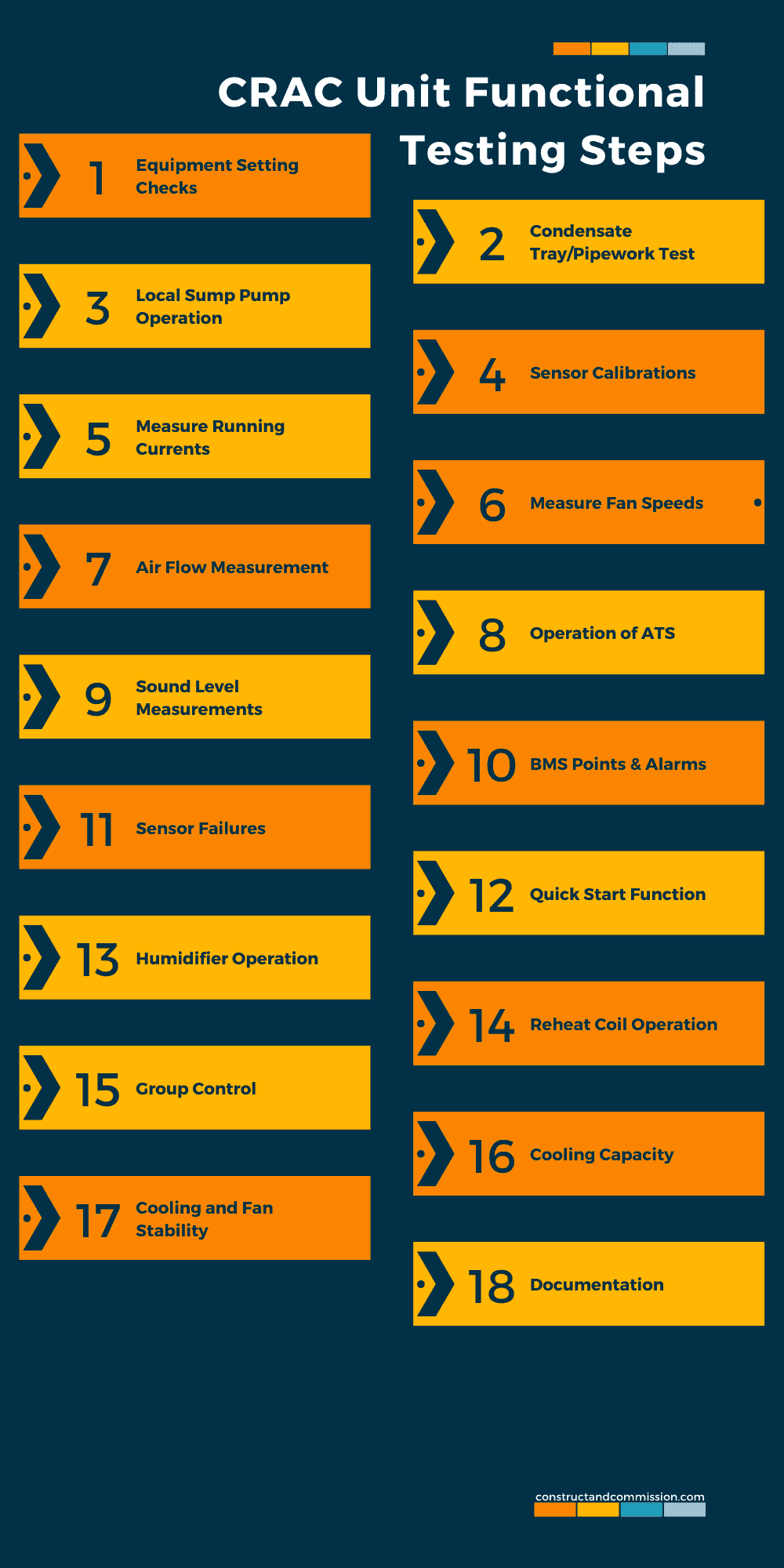
Step 1 – Equipment Setting Checks
From the approved Equipment Setting Document, check and ensure the CRAC Unit system has been set up correctly and the settings are inline.
If there is no setting document, the manufacturer will usually have their ‘standard settings’; these should be checked and verified.
Note: Ensure that all units are set correctly as if not, during the heat load testing, there could be control issues.
Step 2 – Condensate Tray/Pipework Test
To ensure that the condensate tray and the pipework can drain the condensate water produced by the system away, a test will need to be conducted.
With the CRAC Unit [internal & external] off, open the door/panel and pour 2 liters of water into the condensate collection tray.
Wait a few moments to ensure that the water has been removed from the tray by the pipework connected to it.
Once complete, document the test confirming it has passed.
Step 3 – CRAC Unit Local Sump Pump Test
If a local sump pump is installed, this should be tested alongside the condensate tray to ensure it operates and pumps the water away.
Step 4 – Sensor Calibration
Ensure that the sensors controlling and reporting data to/from the CRAC Unit will are fully calibrated.
This is usually carried out with the unit ‘On/Running,’ then placing a calibrated handheld temperature/humidity instrument within 100mm / 3 inches of each sensor and reading.
The handheld reference instrument should have a similar reading to the actual sensor that will be read at the CRAC Unit Display and where required the BMS head end.
Tolerances may be allowed, and this would usually be project-specific, but if not stipulated, then the following can be used:
- Temperature – [+/-0.5 degrees]
- Humidity – [+/-5%]
Step 5 – Running Current of Internal and External Unit Fans
Two running current readings will be taken with the internal CRAC Unit fans running at the following speeds:
- 60%
- 100%
Ensure to measure and document the internal and external units under these loads.
Step 6 – Measure Fan Speed of Internal and External Unit
With the fans set to 100% flow, measure the RPM for each one.
Step 7 – Air Flow Measurement
To ensure sufficient airflow to meet the expected cooling capacity, the Unit will need to be measured and set up.
Use the CRAC unit datasheet to understand the design flow rate required.
Complete the following sequence to measure the flow rate at 100% fan speed [sometimes there will be a requirement to conduct the measurements at 50%, 65% & 75%], check with the specifications:
- Turn on unit.
- Set the fans to operate via the inbuilt controller to 100% flow.
- Using a grid format, take multiple airflow velocity readings, like with normal air balancing. Measure across the face of the CRAC Unit outlet.
- Document each reading in the approved document.
- Calculate the area of the outlet by multiplying its width/length by height.
- Using the formula Q [mass flow rate] = V [velocity] x A [area of grille] calculate the Flow Rate of the Unit [m3/s].
- Ensure flow rate meets the project expectations.
Step 8 – Checking ATS [Automatic Transfer Switch] Change Over
The automatic transfer switch will ensure that the secondary electrical power source is switched over if the primary power source fails.
To complete this test, complete the following sequence:
- Check that correct change over times [upon power fail and power reinstatement] are set correctly to design.
- Check that the CRAC Unit is powered by the Primary Power Source.
- Check that the Secondary Power Source is available at the internal and external unit.
- ATS to be set to ‘Automatic’.
- Simulate loss of power to Primary Power Source [usually at the distribution board breaker or local isolator].
- Check power source has switched from Primary to Secondary Power in the expected time frame and the units restart.
- Once complete reset the Primary Power Source.
- If the design requires that upon resetting of Primary Power the system resets automatically, ensure this has happened in the expected time frame.
- If not reset automatically – reset manually.
Step 9 – Sound Level Test
To ensure that the operational space meets the design sound level requirements, there will be a need to conduct noise/acoustic testing.
The sound levels being read will be related to the equipment datasheets, and if the equipment meets the pre-determined expectations, then the overall room acoustics should not be a problem.
The testing is usually quite simple, if just a general noise test, by running each CRAC Unit at 100% fan speed and then measuring the sound pressure level at around 1 meter from it, ensure that the test is extended to the external unit as well.
Reference the reading taken with the specific acoustic information obtained from the datasheet for the Unit.
Step 10 – BMS Points & Alarms
Using the approved BMS points and Alarm schedule as a reference, simulate and prove all points back to the BMS head-end display.
Cross-reference each point with the CRAC Unit controller/display.
Step 11 – CRAC Unit Sensor Failures
Depending upon the type of sensor failure, the CRAC unit will react differently.
In a Data Hall, if there are multiple units installed, they will be ‘grouped’ and controlled in those groups; if CRAC’s are serving a small room where there are 1 or 2 units, they will usually be controlled individually.
You will need to understand the control logic for the project and the different areas they are installed. This information can be obtained from the material/technical submission [return air control/supply air control].
Once understood, simulated failures can be conducted on the following sensors:
- Return air temperature sensor
- Supply air temperature sensor [controlling the cooling valve]
- Remote temperature sensor
- Remote humidity sensor
Step 12 – Quick Start Function
To ensure minimum downtime is experienced when there is a total power failure to the CRAC Unit, the specification will usually require a ‘Quick Start’ Function.
The following sequence can be completed to test this:
- With the CRAC unit running normally,
- Power off the indoor and outdoor unit, letting it shut down,
- Restart the units and measure the time taken for the fan to start with a stopwatch,
- Then time how long for the units control board to fully boot up,
- Ensure CRAC Unit is running normally,
- Compare the time taken for the unit to start up with the design requirements.
Step 13 – Humidifier Testing
Where there is a humidifier installed in the CRAC unit, the following test sequence can be conducted:
- CRAC Unit running,
- Manually adjust the humidity setpoint above the current reading at the return side of the unit to activate and start it,
- Check that the humidifier has started and steam is being generated,
- With the humidifier running, measure the running current and cross-reference with the material data sheet,
- Manually adjust the humidity setpoint to below the value being measured,
- Check that the humidification process has been stopped and no steam is being generated.
Step 14 – Reheat Coil
If there is a reheat coil installed, complete the next series of tests:
- CRAC Unit running,
- Manually adjust the temperature setpoint above the current reading at the return/supply side of the unit to activate and start it,
- Check that the reheat coil has started,
- Measure the running current and cross-reference with the material data sheet,
- Manually adjust the temperature setpoint to below the value being measured,
- Check the heater has stopped.
Step 15 – Group Control Test
For group control information and testing, see our article ‘GROUP CONTROL | CRAH & CRAC Units.’
Step 16 – Cooling Capacity Testing
Finally, to ensure that the CRAC Unit can meet its cooling design objectives, a ‘cooling’ capacity test will need to be conducted to ensure that the overall capacity of each Unit meets its datasheet/material/technical submission.
To save time, multiple units are sometimes tested together.
The test will utilize a temporary load bank, and these should be procured and installed before testing starting as it can be a bit of a logistical nightmare.
You should ensure that they are included within the CRAC Unit manufacturer/Vendors scope.
To complete the test, the following sequence can be used:
- Room structure to be completed, permanent doors, windows, walls, hot aisle, cold aisle,
- Room to be clean and free of debris,
- Room environment is stable,
- Ensure electrical supplies to the CRAC Unit/s and temporary loaders will be stable throughout the testing,
- Ensure the refrigeration system will be stable throughout the testing,
- Check the BMS and control systems will be stable throughout the testing,
- Install and set up temporary loaders, where required to the required loadings
- Turn CRAC Unit/s on and input setpoint for controlling fan speeds and cooing valves [use the design setpoints if not sure],
- With CRAC On and operating, introduce load to the space by switching on the temporary loaders,
- Increase load slowly until the load requirements are met, try to keep the return air temperature at the CRAC the same as noted on the datasheet,
- Once 100% load is achieved, measure the following:
- Airflow rate and volume
- Supply / Return air temperature
- Supply / Return air humidity
Once all the readings have been obtained, calculate the total cooling capacity [KW]
With the units still operating document and conduct the following checks and tests on the external unit:
- High pressure cut out,
- Low pressure cut out,
- Compressor suction and discharge pressure,
- Evaporator entering and leaving coil temperature [wet bulb and dry bulb]
- Condenser entering and leaving coil temperature [wet bulb and dry bulb]
Step 17 – Stability test
We would run this test to make sure all is ok with the operation of the CRAC unit.
Sometimes the units can be seen to ‘hunt,’ which means that the controls and valves are unstable, constantly moving from open to closed.
This can create temperature fluctuations in the data hall due to air supply and cause significant issues during the Heat Load Testing.
The following sequence can be used:
- Room structure to be completed, permanent doors, windows, walls, hot aisle, cold aisle,
- Room to be clean and free of debris,
- The room environment is stable,
- Ensure electrical supplies to the CRAC internal and external units and temporary loaders will be stable throughout the testing,
- Check the BMS and control systems will be stable throughout the testing,
- Install and set up temporary loaders, where required to the required loadings
- Turn CRAC Unit/s on and input setpoint for controlling fan speeds and cooling valves [use the design setpoints if not sure],
- With CRAC On and operating introduce load to the space by switching on the temporary loaders,
- Increase load slowly until meet the 50% load requirement,
- Once 50% load is achieved, review the CRAC Trends and Supply Air Temperature to ensure neither are ‘hunting’,
- If found to be hunting, have the manufacturer review the settings and make any required adjustments,
- Rerun the test until the trends are stable,
- Once completed the 50% load test, increase to 100%
- Once 100% load is achieved, review the CRAC Trends and Supply Air Temperature to ensure neither are ‘hunting’,
- If found to be hunting, have the manufacturer review the settings and make any required adjustments,
- Rerun the test until the trends are stable.
Step 18 – Documentation
Ensure all documentation is completed and the testing data is approved and signed off by relevant parties.
⬛ Related Articles
GROUP CONTROL | CRAH & CRAC Units
CRAH UNITS | What are they?
CRAC UNIT | Pre-Functional CheckList
CRAC Unit vs CRAH Unit | What’s the difference?
CRAH UNIT | Pre-Functional CheckList
CRAH UNIT | Functional Testing Example + Template