To allow the cooling towers to operate correctly, in line with the design and efficiently, various systems will need to be connected to allow them to work. Depending upon how the towers are installed will mean different configurations would be required.
The pipework that is commonly connected to the towers would be:
- Condenser water return [1]
- Condenser water supply [2]
- Cooling tower bypass [3]
- Equalization line / balance pipe [4]
- Make up water [5]
- Water sampling [6]
- Blow down / bleed water [7]
- Overflow [8]
- Filtration [9]
- Drainage [10]
- Plate Heat Exchanger [11]
Standard equipment and instruments that are installed would cover:
- Isolation valves
- Regulating valves
- 2 way control valves
- 3 way control valve
- Mechanical float valve
- Pressure gauges
- Temperature sensors
- Side stream filter
- Chemical treatment pumps
- Flow meters
- Condenser water pump
- Plate heat exchangers
- Water cooled chiller
Below we will provide a high-level overview of the cooling tower piping design covering each of the pipework connections above, including some diagrams.
Cooling Tower Typical Piping Diagram
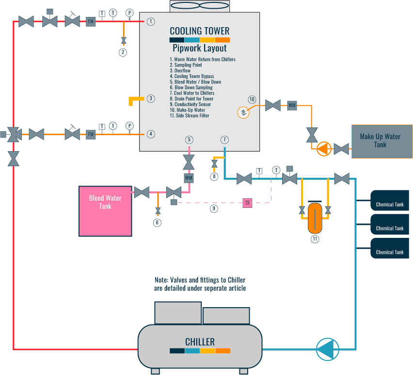
Condenser Water Return Pipework [1]
The cooling tower return pipework is installed to transport the warm water from the condenser side of the water-cooled chiller to the cooling tower, with the flow being provided by the condenser water pumps that are installed on the supply side of the tower [tower to chiller] to move the water around the system.
Return Pipework Configuration
The pipework can be directly connected between the chiller and the tower or, if multiple towers and chillers are used, a common header would generally be utilized.
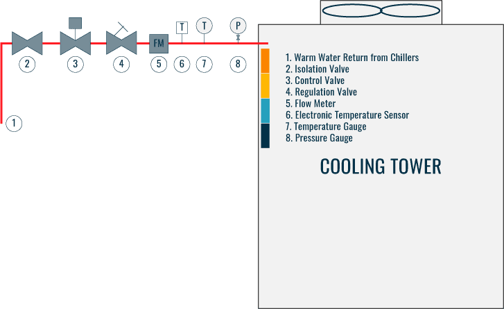
There are occasions when a plate heat exchanger would be used and installed between the chiller and tower if the tower is installed at a lower level than the water-cooled chiller, this is described in high-level later in this article.
Return Pipework Material
The pipework, if an open cooling system, would be manufactured from one of the following materials:
- Carbon steel pipe work and hot dipped galvanized
- Galvanized pipe work [all the pipe work is made from this]
Alternatively, there is a method of
- Carbon steel with the internal painted [on larger pipework]
The galvanizing provides protection from accelerated corrosion and pipework degradation when the system is open and, although should be managed via chemical treatment and blowdown/filtration systems, there is always a risk.
Return Pipework Insulation
Depending on the design [temperature of the system, risk of freezing] and the location the system is installed, pipework insulation may or may not be required. If it is required, this is usually a fiberglass material covered in an aluminum foil [rockwool] or a type of kooltherm which is a more rigid material.
If installed externally and or within a plant room type area there will possibly be a need to protect it. This can be done with a hammer lad or similar material.
If using insulation, ensure that there will be no issues with the pipework material you are using.
Return Pipework Valves
There are 4 types of valves that would need to be installed:
- Isolation valves – usually the butterfly type valve, these will be installed prior to the connection to the cooling tower to allow isolation of the equipment and system if needed.
- Regulating valves – these will usually be installed at the cooling tower to allow regulation / control of the condenser water flow to the nozzles / fill pack basin.
- 2 port control valves – to allow the control of the water to the cooling tower [on/off].
Ancillaries
For the ancillaries that are required and installed, the following would usually be expected:
- Flow meter.
- Manual pressure gauge – this is the standard type of gauge, not calibrated, that is used to understand the pressure of the system near the tower locally.
Condenser Water Supply Pipework [2]
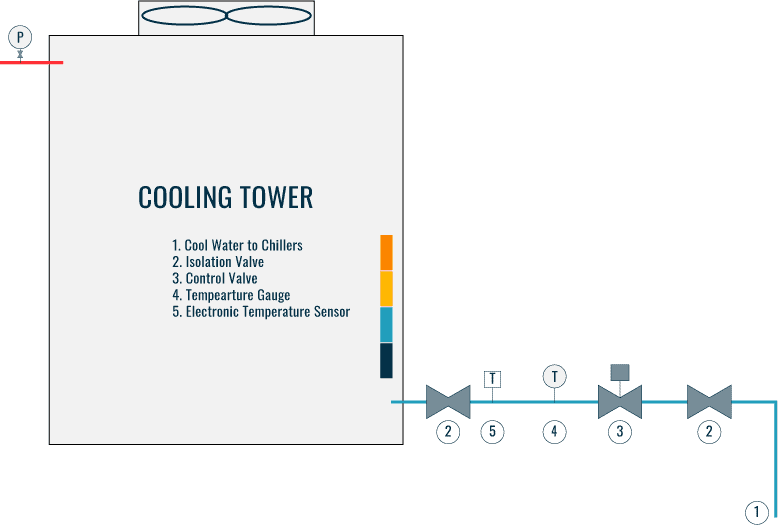
The cooling tower supply pipework is installed to create the condenser water loop transporting the cooler water, that has been created from the evaporative cooling process of the cooling tower to the condenser side of the water-cooled chiller, with the flow being provided by the condenser water pumps that are installed.
Supply Pipework Configuration
As with the return pipework above, the supply pipework can be directly connected between the tower and the chiller or, if multiple towers and chillers are used, a common header would generally be utilized.
Supply Pipework Material
The material used will be the same as the return condenser pipework, above.
Supply Pipework Insulation
As with the return pipework, depending on the design [temperature of the system, risk of freezing], and the location the system is installed into, pipework insulation may or may not be required. If it is required, this is usually a fiberglass material covered in an aluminum foil [rockwool] or a type of kooltherm, which is a more rigid material.
If installed externally and or within a plant room type area there will possibly be a need to protect it. This can be done with a hammer lad or similar material.
If using insulation, ensure that there will be no issues with the pipework material you are using.
Supply Pipework Valves
There are 2 types of valves that would need to be installed:
- Isolation valves – usually the butterfly type valve, these will be installed prior to the connection to the water cooled chiller and the cooling tower to allow isolation of the equipment and system if needed.
- 2 port control valves – to allow the control of the water from the cooling tower [on/off]
Ancillaries
For the ancillaries, the following would usually be expected:
- Electronic temperature sensor – to allow monitoring of the return condenser water temperature, these would be installed near the
flow meter and connection to the tower. Allowing data gathering and used for the energy calculations and provide information to control the cooling system. - Manual temperature gauge – this is the standard type of gauge, not calibrated, that is used to locally understand the temperature of the water returning to the tower. It should be installed near the electronic temperature sensors and
flow meter .
Cooling Tower Bypass Pipework [3]
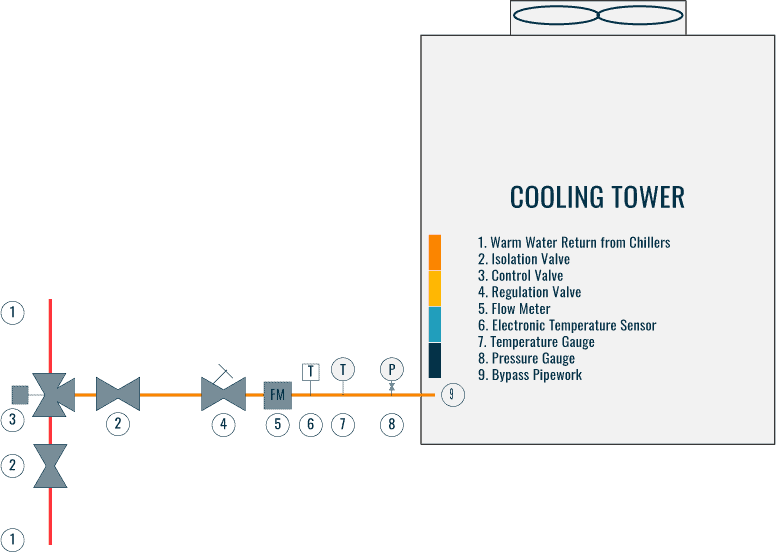
A cooling tower bypass is used mainly in colder climates, where there is risk that the supply water temperature to the condenser side of the chillers is not at the required temperature set point, i.e its to cold system
A bypass mixes some of the warm return water with the water being supplied from the tower increasing its temperature.
Bypass Pipework Configuration
The return from the system will tee into the supply side of the condenser water system, between the pumps and cooling tower, via a 3 port valve and small amount of additional pipework.
Bypass Pipework Material
The material used will be the same as the return condenser pipework, see above.
Bypass Pipework Insulation
As with the supply pipework, depending on the design [temperature of the system, risk of freezing], and the location the system is installed into, pipework insulation may or may not be required. If it is required, this is usually a fiberglass material covered in an aluminum foil [rockwool] or a type of kooltherm, which is a more rigid material.
If installed externally and or within a plant room type area there will possibly be a need to protect it. This can be done with a hammer lad or similar material.
If using insulation, ensure that there will be no issues with the pipework material you are using.
Bypass Pipework Valves
There are 3 types of valves that would need to be installed:
- Isolation valves – usually the butterfly type valve, these will be installed around the control valve to allow for isolation if needed in the future.
- Regulating valves – these will usually be installed to allow regulation / control of the supply water flow with the return.
- 3 port control valve – to allow the control of the water temperature
Ancillaries
- flow meter.
- Manual pressure gauge – this is the standard type of gauge, not calibrated, that is used to locally understand the pressure of the system near the tower.
Balance Pipework / Equalization Line [4]
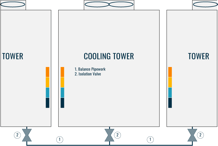
The equalization line/balance pipe is used when there are multiple towers/cells working together within a condenser system, to ensure that if there is an imbalance in the system, then the pipework will allow it to equalize itself out between the towers.
Balance Pipework Configuration
Pipework would usually be connected to the bottom or side of each tower sump/basin and piped as a common header behind a common header linking all towers together.
Balance Pipework Material
The material used will be the same as the return condenser pipework, see above.
Equilizer Pipework Insulation
Generally, the insulation will not be required unless there is a risk of freezing. If it is required, this is usually a fiberglass material covered in an aluminum foil [rockwool] or a type of kooltherm, which is a more rigid material.
If installed externally and or within a plant room type area there will possibly be a need to protect it. This can be done with a hammer lad or similar material.
If using insulation, ensure that there will be no issues with the pipework material you are using.
Equalizer Pipework Valves
There is only 1 type of valve that would need to usually be installed:
- Isolation valves – usually the butterfly type valve, these will be installed near to each tower connection to allow for isolation if needed in the future.
Ancillaries
Not many ancillaries would be used for this system, as is just pipework connecting towers together.
Make Up Water Pipework [5]
Makeup water is introduced into the sump/basin, usually via a float valve, of the cooling tower to replace the water that is lost through the tower due to evaporation, drift, and blowdown.
We have written more on this system in our article ‘****’.
Make Up Water Configuration
It’s a very straightforward setup. The makeup water is connected above the required cooling tower basin water line, within the tank, there is usually a float valve that will be used to manage the water filling process.
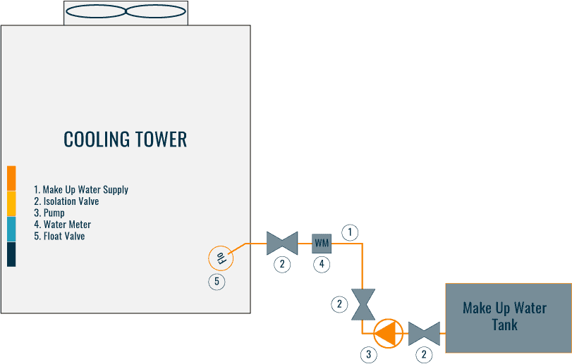
From the tower looking back down the system, there will usually be a water tank and pumps, as explained later in this section.
We have written more on this system in our article ‘****’.
Make up Water Pipework Material
The pipework material used could be one of the following:
- Copper
- Galvanized
- Plastic
Make Up Water Pipework Insulation
Externally the pipework would not require to be insulated unless there is a risk of freezing.
Internally, there could be a requirement due to the cooler water temperature that may be within the pipework creating condensation on the pipework, risking damage to internal structures, etc.
Where required, this is usually a fiberglass material covered in an aluminum foil [rockwool] or a type of kooltherm, which is a more rigid material.
If installed internally / externally and or within a plant room type area there will possibly be a need to protect it. This can be done with a hammer clad or similar material.
If using insulation, ensure that there will be no issues with the pipework material you are using.
Make Up Water Pipework Valves
There are 3 types of valves that would need to usually be installed:
- Isolation valves – usually the 1/4 turn globe type valve, rated for domestic services will be utilized. These will be installed near to the float valve and pump / water tank if used.
- Float Valve – This is the most common way of monitoring the water level within the tank and activating to top up the tower basin level. Would be similar operation to a water tank float valve.
- Control Valve [if float valve is not used] – a control valve maybe selected over the float valve which would utilize level sensors within the tower sump / tower basin to monitor the level. Once the water level is needing to be topped up, the level sensors will send a signal to the control valve to open, allowing fresh water to enter the system.
Ancillaries
- Pump – Usually, due to the installation of the make up water tank, sometimes lower than the tower basin, there may need to be a requirement for the Make Up Water to be pumped. The pumps usually consist of a packaged unit that is supplied with all control and a set of run and standby pumps [2 pumps].
- Storage Tank – A water storage tank is often used to allow the make up water to be stored and also to provide an air gap / break between the the system and if connected to a fresh water mains supply to stop backwash / contamination.
- Water Meter – this is installed prior to the connection to the cooling tower to allow the water usage to be monitored and logged.
- Water Supply to Tank – Where a storage tank is used there will be a requirement for a water supply to be connected to the water tank. This will usually be controlled in the same manner as the make up water feed to the basin, via a float valve or electronic control valve with applicable level sensors.
- Controls – If using a pump / control valves, there would generally be a requirement for controls to provide the logic to operate the system inline with the design expectations.
Water Sampling Point [6]
A water sampling point is installed into the tower system to allow water to be collected and tested for its quality and to ensure it is meeting the system/code/manufacturer requirements.
Water Sampling Point Pipework Configuration
The most common place to install the sampling point is at the pipework just before it enters the tower by the nozzles / high-level warm water basin.
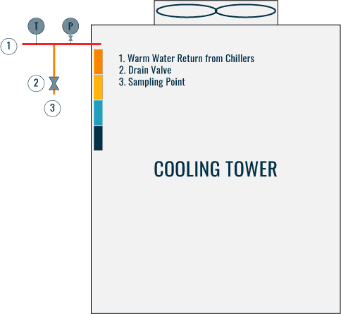
The size would not need to be too big [15 – 22mm] and will require a valve/tap to allow the collecting of samples.
Water Sampling Material
The materials would be the same as the condenser water return pipework, carbon steel hot-dipped galvanized, galvanized, or carbon steel with an internally painted surface, to provide protection for corrosion, etc.
Water Sampling Insulation
The sampling point will be insulated as per the return pipework to the tower.
Water Sampling Valves
Just 1 valve will be required or could be a tap, to allow the collection of the samples.
Ancillaries
There will generally not be any ancillaries for the sampling point.
Blow Down / Bleed Water Pipework [7]
Blowdown pipework is required to allow the removal of water from the condenser water system for replacement with the makeup water, controlling the total dissolved solids [TDS] build up with increases the risks of scaling and corrosion.
We have written more on this system in our article ‘****’.
Blow Down / Bleed Water Pipework Configuration
The pipework can be connected directly to the cooling tower basin or the supply pipework, near the tower connection, that is feeding the water-cooled chillers with the conditioned water, and will be controlled by a water conductivity sensor, that is monitoring the water quality in the pipework serving the chillers.
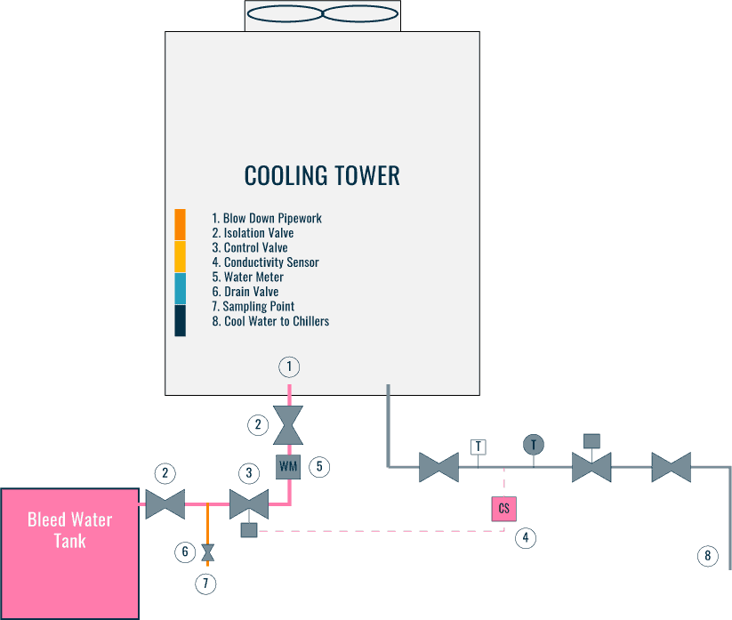
Within the pipework configuration will be a control valve that, once activated from the conductivity sensor, will allow a set quantity of water to be drained and thus allowing clean water from the above ‘Make-Up Water System’ to replenish and help maintain the water quality.
The pipework will be piped directly to drain, if allowed by code or stored in a holding tank where it would be re-processed and recycled back into the cooling tower make-up water system for future use, saving water.
A gravity system would usually be employed for this.
Bleed Water Pipework Materials
The materials would be the same as the condenser water return pipework, carbon steel hot-dipped galvanized, galvanized, or carbon steel with an internally painted surface, to provide protection for corrosion, etc.
Blow Down Pipework Insulation
The pipework will be insulated as per the return pipework to the tower.
Blow Down Valves
There are 2 types of valves that would usually be installed:
- Isolation valves – usually the 1/4 turn globe type valve, rated for domestic services will be utilized. These will be installed near to the tower and water tank if used.
- 2 Way Control Valve – a control valve is used to control the discharge from the basin through the pipework. It will will be activated by the signal sent from the conductivity sensor, when required to operate.
Ancillaries
- Storage Tank – A storage tank is often used to allow the blow down water to be stored for recycling back into the system once treated / the correct quality.
- Water Meter – this is installed prior to the connection to the water tank to allow the monitoring of the quantity of the blowdown to be monitored.
- Conductivity Sensor – Installed into the return pipework that is moving the cooled water to the water cooled chillers, the conductivity meter will monitor the total dissolved solids and will activate the control valve to ‘blow down’ the system.
- Controls – there will be a requirement for some simple controls to allow the conductivity meter to activate the 2 way control valve.
Overflow Pipework [8]
An overflow is installed above the basin water level, to help control and dispose of any overfilling of the cooling tower.
Overflow Pipework Configuration
Pretty simple, and connected to the cooling tower casing, above the designed operational water level.
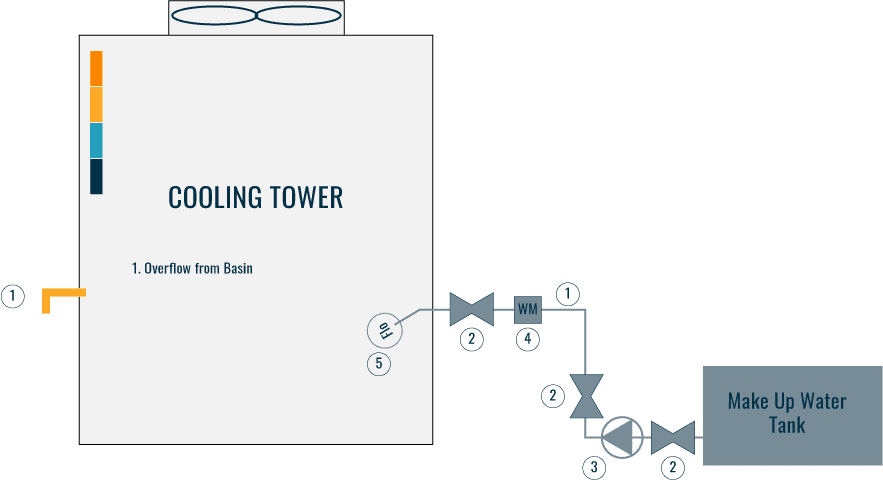
It will be visible so that if an overflow does happen, it will be very obvious to any engineers walking past.
Overflow Material
Usually manufactured from UPVC / GRP plastic.
Overflow Insulation
None required.
Overflow Valves
None required.
Overflow Ancillaries
None required.
Cooling Tower Side Stream Filtration Pipework [9]
Filtration is used at the cooling towers to help remove any impurities and debris from the system that may enter through the cooling process.
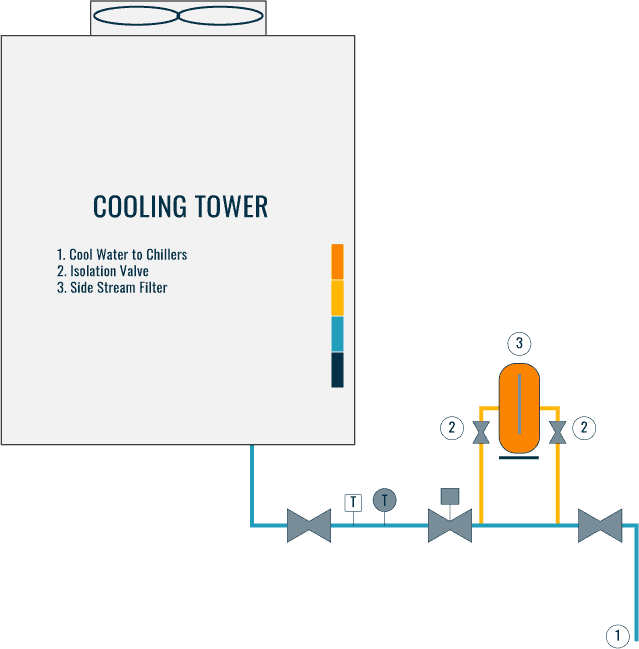
The most common method is to use a side stream filtration system that consists of the following equipment:
- Pipework
- Side stream filter
- Valves
The filter is installed outside the main condenser water system, as seen in the below simple drawing, connected to the pipework from the tower basin feeding the water-cooled chillers with cool water.
Drainage Pipework [10]
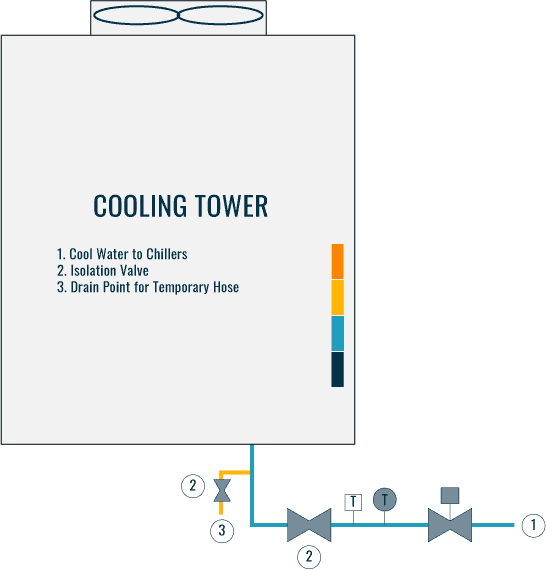
To enable drawing in the cooling tower, drainage pipework will need to be installed to facilitate this. The pipework would usually be connected to the bottom of the tower basin or before the isolation valve on the supply pipework to the chillers.
Drainage Pipework Configuration
Installed as a short piece of pipework with a valve and fitting to connect a temporary hose. The hose will then be run to where the water will be disposed of.
Drainage Pipework Material
Usually manufactured from a similar material to the supply/return pipework above.
Drainage Pipework Valves
Only 1 valve is needed to ‘open’ and ‘close’ for draining.
Drainage Ancillaries
Maybe a temporary hose will be needed, to run the water to the point of discharge.
Cooling Tower connected to a Plate Heat Exchanger [11]
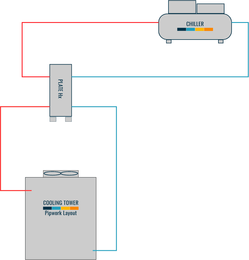
In some instances where the cooling tower is installed at a lower level than the chillers, there is a requirement for a plate heat exchanger.
The plate heat exchanger is installed between the chillers and the towers to stop the condenser water from running back to the towers, and flooding them, losing all the water from the system.
If used they will bring some complications, such as:
- Pipework cleaning and flushing
- Water Balancing
- Sequence of Operations / Controls
Below is a simple diagram showing a configuration of using a plate heat exchanger within a condenser system.
⬛ Related Articles
COOLING TOWER | Pre-Commissioning Checklist and download
COOLING TOWER | Preventative Maintenance Inspections
MAKEUP / BLOW DOWN | Cycles of Concentration
COOLING TOWER | Inspecting & Cleaning Overview
COOLING TOWERS | All 38 components explained
COOLING TOWER | Types of Towers and Ponds

